
Breath and head tilt controlled prosthetic limb

a prosthetic limb and head tilt technology, applied in the field of functional limb prosthetics, can solve the problems of complex control system, invasiveness, and cost prohibitive for most people, and achieve the effect of reducing the cost of control system

Inactive Publication Date: 2016-05-05
SCHULTZ MARIN RENNER
View PDF3 Cites 9 Cited by
  • Summary
  • Abstract
  • Description
  • Claims
  • Application Information

AI Technical Summary

Benefits of technology

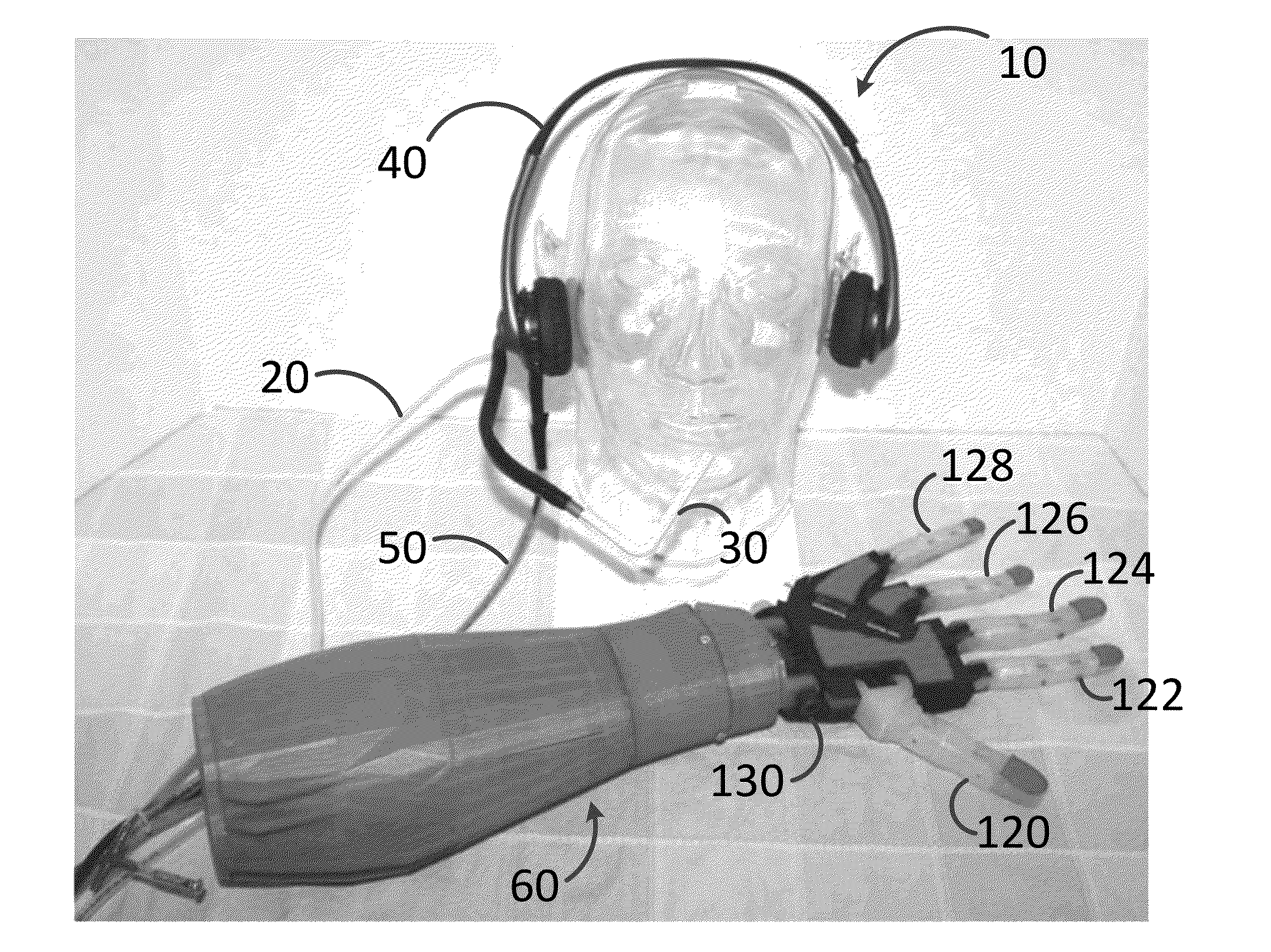
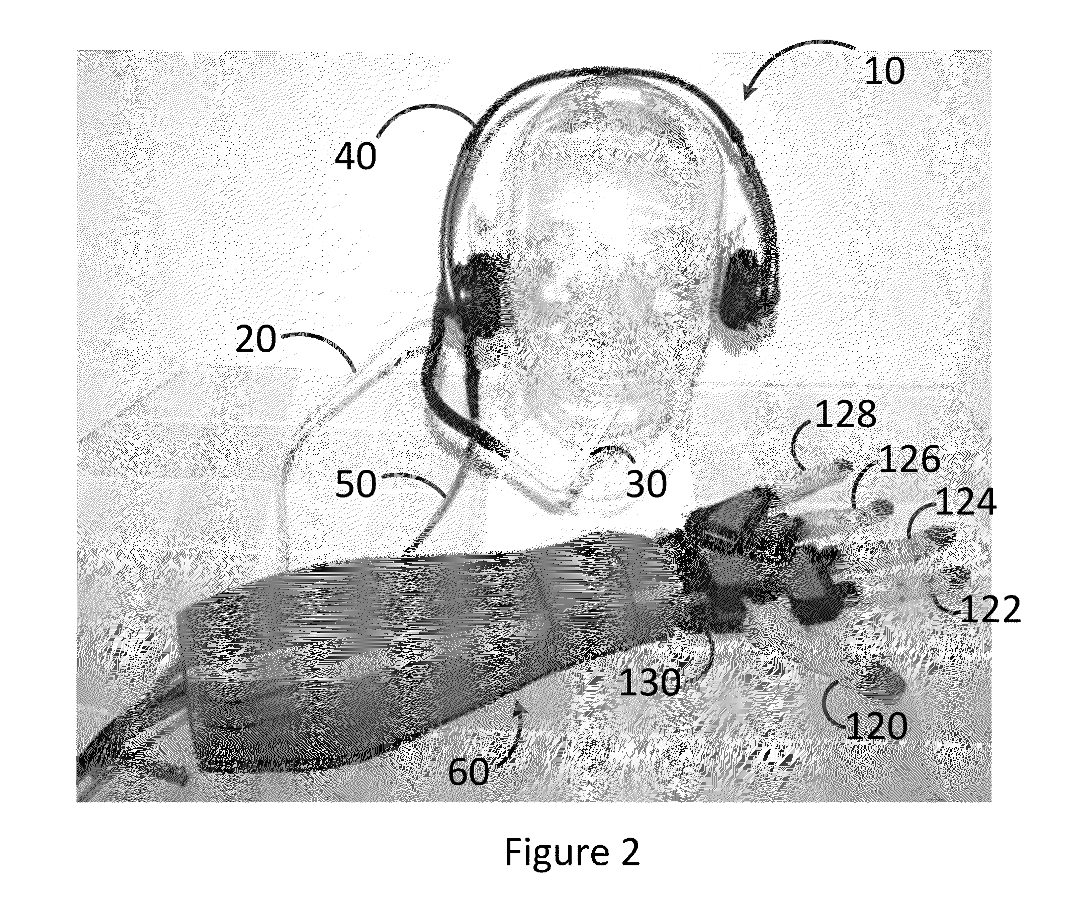
The patent describes an input control device for a powered prosthetic limb that uses air pressure and head tilting motion to control the movement of the limb. The device includes a breath inlet and a motion sensor that convert the air pressure and head tilting motion into electrical signals. These signals are then processed into positional data for the limb's digit-actuators and wrist-actuator. The device can be controlled to actuate the digit-actuators in a closed position and to rotate the wrist-actuator in proportion to the user's head tilting motion. The technical effect of this invention is to provide a more intuitive and efficient means for controlling the movement of a prosthetic limb.

Problems solved by technology

Such control systems are complex and can be invasive, requiring implantation of the apparatus into the patient's body.
As well, these types of control systems are expensive and cost prohibitive to most of the population.
Accordingly, access to many forms of existing powered prosthetic limbs is limited.

Method used


Image

  • Breath and head tilt controlled prosthetic limb
  • Breath and head tilt controlled prosthetic limb
  • Breath and head tilt controlled prosthetic limb

Examples


example 1

Prototype Breath, Head-Tilt Controlled Prosthetic Hand

[0054]A low-cost, open-source, 3D printed prosthetic hand prototype controlled by a breath-pressure sensor and dual axis accelerometer was developed. Finger movements and wrist rotation were made controllable by separate control systems. A breath-pressure sensor was used to control finger movement and a dual axis accelerometer implanted in a headset was used to control wrist rotation.

Hand

[0055]Materials and Methods[0056]3D printed PLA plastic hand, wrist and forearm (open source design by inMoov)[0057]Various nails, screws, and bolts[0058]Locktite Super Glue (gel and liquid)[0059]Spiderwire 100 lb test braided fishing line[0060]5—Hobby King HK-15298 90°, high current (14 lb torque) servo motors (4.8-7V)[0061]1 Parallax standard 180° servo motor (4.8-6V)[0062]1 USB cable[0063]Hookup wire[0064]4 in. small plastic fuel-line tubing[0065] 3 / 16 in. outer diameter flexible plastic tubing[0066]3-way plastic tubing air splitter[0067]Green...


PUM


Abstract

In alternative embodiments, provided is an internally powered prosthetic limb and method for controlling same, offering hands-free control of a prosthetic limb. The internally powered prosthetic limb controlled by an input control device, comprising: a breath inlet configured to receive air pressure exerted from a user's mouth to be converted into a first electronic signal, wherein the first electronic signal is proportional to the exerted pressure; a motion sensor configured to sense tilting of the user's head and operable to convert the user's head tilting motion into a second electronic signal, wherein the second electronic signal is proportional to the user's head tilting motion; and a processor in communication with the breath inlet and the motion sensor, the processor operable to convert the exerted air pressure into the first electronic signal and further process the first electronic signal into first positional data for transmission to a plurality of digit-actuators in the prosthetic limb, the processor further operable to process the second electronic signal into second positional data for transmission to a wrist-actuator in the prosthetic limb; wherein the plurality of digit-actuators in the prosthetic limb can be controllably actuated in proportion to the air pressure exerted by the user, and the wrist-actuator can be controllably actuated to rotate in proportion to the head tilting motion of the user.

Description

RELATED APPLICATIONS[0001]This U.S. Utility patent application claims the benefit of priority under 35 U.S.C. §119(e) of U.S. Provisional Application No. 62 / 073,736, filed Oct. 31, 2014. The aforementioned application is expressly incorporated herein by reference in its entirety and for all purposes.TECHNICAL FIELD[0002]The present invention relates to the field of functional limb prosthetics and, in particular, to an internally powered prosthetic limb that is controlled by the user's breath and head tilt.BACKGROUND OF THE INVENTION[0003]A functional limb prosthetic replaces the function of an amputated or congenitally malformed or missing limb in order to offer functionality to the individual. Technological advances have resulted in vast improvements in the functionality of such prosthetics. Where functional limb prosthetics were once limited to being mechanically controlled through cables and harnesses strapped to the individual, internally powered limb prosthetics that use a batt...

Claims


Application Information

Patent Timeline
Patent Type & Authority Applications(United States)
IPC IPC(8): A61F2/68A61F2/58
CPCA61F2/68A61F2002/6836A61F2002/704A61F2/583A61F2/76A61F4/00A61F2002/5061A61F2002/701A61F2002/7615A61F2002/7625A61F2002/764A61F2002/7655A61F2/70
Inventor SCHULTZ, MARIN RENNER
Owner SCHULTZ MARIN RENNER
Learn More