
Auxiliary Power Supplies

a technology of auxiliary power supply and power supply, which is applied in the direction of dc-dc conversion, power conversion system, electrical apparatus, etc., can solve the problems of prohibitively large dissipation, inconvenient voltage regulation circuitry, and power dissipation within the resistor or linear regulator, so as to achieve the effect of suppressing the flow and highest efficiency

Active Publication Date: 2016-04-28
MICROCHIP TECH INC
View PDF9 Cites 0 Cited by
  • Summary
  • Abstract
  • Description
  • Claims
  • Application Information

AI Technical Summary

Benefits of technology

The present invention is about a circuit for supplying current that has several technical effects. It has a low component count, is suitable for both stages of switching regulator operation, can handle both potentials (nonswitching and switching), and operates at high efficiency in the switching stage. It also has a low impedance in the switching stage to minimize dissipation and allows for the integration of the auxiliary supply switch within power management ICs built on low voltage processes.

Problems solved by technology

Some circuits may be quite simple, such as a gate driver, others may be quite complex, such as the main control circuit.
The major drawback is the dissipation of power within the resistor or linear regulator.
The dissipation becomes prohibitively large in offline switching regulators, thus requiring the use of other circuit solutions for the supply of current.
A common drawback is a dependence of the auxiliary supply voltage on operating conditions of the switching regulator, such as loading, input voltage, or output voltage, the dependence at times requiring additional voltage regulation circuitry.

Method used


Image

  • Auxiliary Power Supplies
  • Auxiliary Power Supplies
  • Auxiliary Power Supplies

Examples


Embodiment Construction

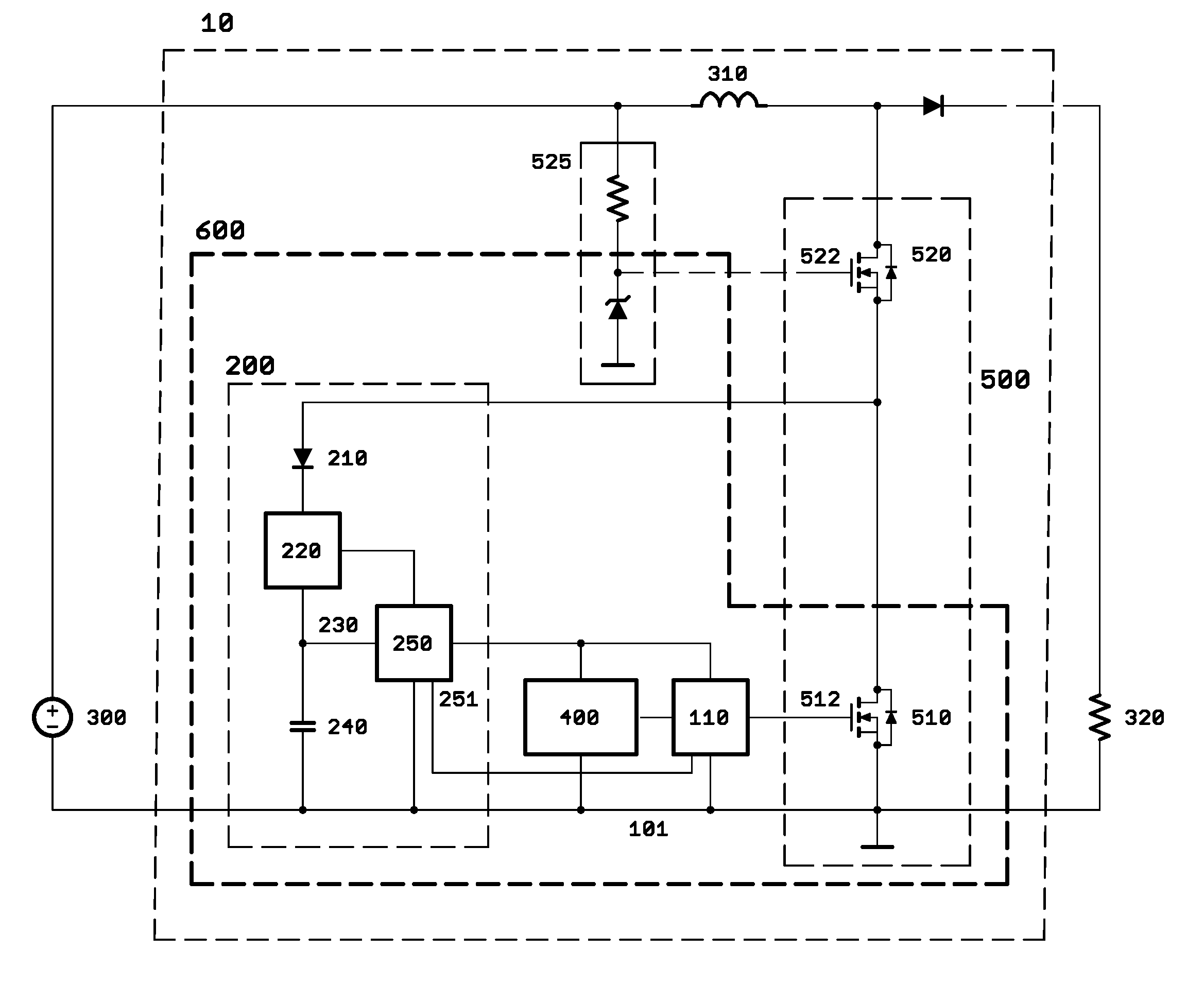
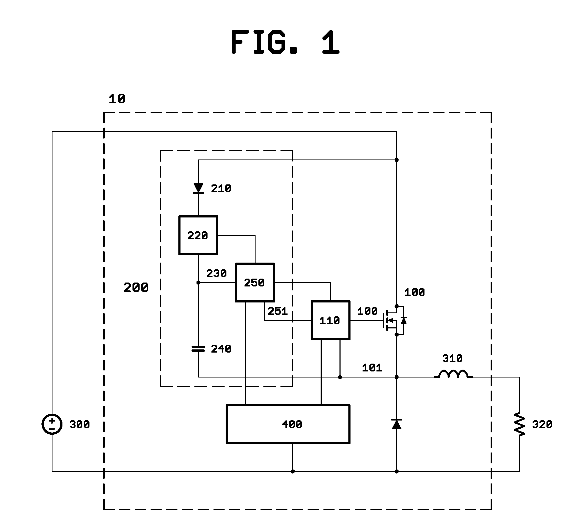
[0031]A first exemplary embodiment employs the principles of the invention in the setting of a buck regulator, specifically of the type where the switch, the associated gate driver circuit and associated auxiliary supply are configured with a common node carrying a switching potential.

[0032]The principles of the invention are applied to the supply of current to the auxiliary supply of the gate driver circuit. This particular embodiment exemplifies the use of the invention where the supply of current is provided in both the nonswitching and switching stages of buck regulator operation and where the common node carries a switching potential.

[0033]FIG. 1 depicts the exemplary buck regulator 10. Switch 100 is of the FET type. The source of the FET, is connected to node 101, commonly known as the switching node. Switch 100 is driven by gate driver circuit 110 at gate 102 of FET 100, the gate driver circuit also connected to node 101. Auxiliary supply 200 powers gate driver circuit 110, t...


PUM


Abstract

The invention relates to methods for supplying current to an auxiliary power supply, where the auxiliary supply is connected in parallel to a first switch of a switching regulator and the parallel connection of the auxiliary supply comprises a diode and a second switch.

Description

CROSS REFERENCE TO RELATED APPLICATION[0001]This application is a divisional of U.S. application Ser. No. 13 / 924,302, filed on Jun. 21, 2013, and titled “Auxiliary Power Supplies,” which is incorporated herein by reference.TECHNICAL FIELD[0002]The invention relates to auxiliary power supplies.BACKGROUND OF THE INVENTION[0003]Switching regulators for the conversion of electrical power are well known. Such switching regulators generally include various control circuits. Some circuits may be quite simple, such as a gate driver, others may be quite complex, such as the main control circuit.[0004]Invariably, a control circuit requires a supply of power of its own. A supply for control circuits commonly goes by a name such as auxiliary supply, housekeeping supply, bias supply, VDD supply or VCC supply.[0005]An auxiliary supply by itself requires a supply of current for operation. There is a general need for circuits providing the supply of current at lowest cost, smallest circuit size and...

Claims


Application Information

Patent Timeline
Patent Type & Authority Applications(United States)
IPC IPC(8): H02M1/08H02M1/36
CPCH02M1/36H02M1/08H02M3/158H02M1/0006H02M1/0045
Inventor TAN, MARCMEDNIK, ALEXANDERKRUGLY, SIMONWAI-SUM CHAN, WILSON
Owner MICROCHIP TECH INC
Learn More