
Camera having a display member

Active Publication Date: 2016-04-28
CANON KK
View PDF4 Cites 1 Cited by
  • Summary
  • Abstract
  • Description
  • Claims
  • Application Information

AI Technical Summary

Benefits of technology

The invention provides a display member for a finder that has improved clarity and visibility of the index. This is achieved by reducing unevenness of the outer peripheral contour of the frame. Additionally, a mold processing method is provided for the frame line of the display member, and a camera that uses the display member is also provided. The visibility of the superimposed function is not only improved, but the density of the frame line is also made uniform to further improve visibility.

Problems solved by technology

However, the conventional superimposed function formed by metal film deposition has had a problem that manufacturing costs are high and quality of visibility is not satisfactory due to occurrence of misalignment of vapor disposition.
However, there is a problem that a conventional optical flat plate into which Japanese Patent Application Laid-Open No. 2005-338662 and Japanese Patent Application Laid-Open No. 2008-180970 are incorporated together has the flame line inferior in visibility. FIGS. 10A and 10B illustrate a conventional optical flat plate, of which FIG. 10A is a cross sectional view of a frame line and a reflective prism group on an optical flat plate and FIG. 10B is a view illustrating a finder visual field.
Accordingly there has been a problem that a difference in color density in the frame line becomes remarkable so that visibility of the frame line is deteriorated.

Method used


Image

  • Camera having a display member
  • Camera having a display member
  • Camera having a display member

Examples


embodiment 1

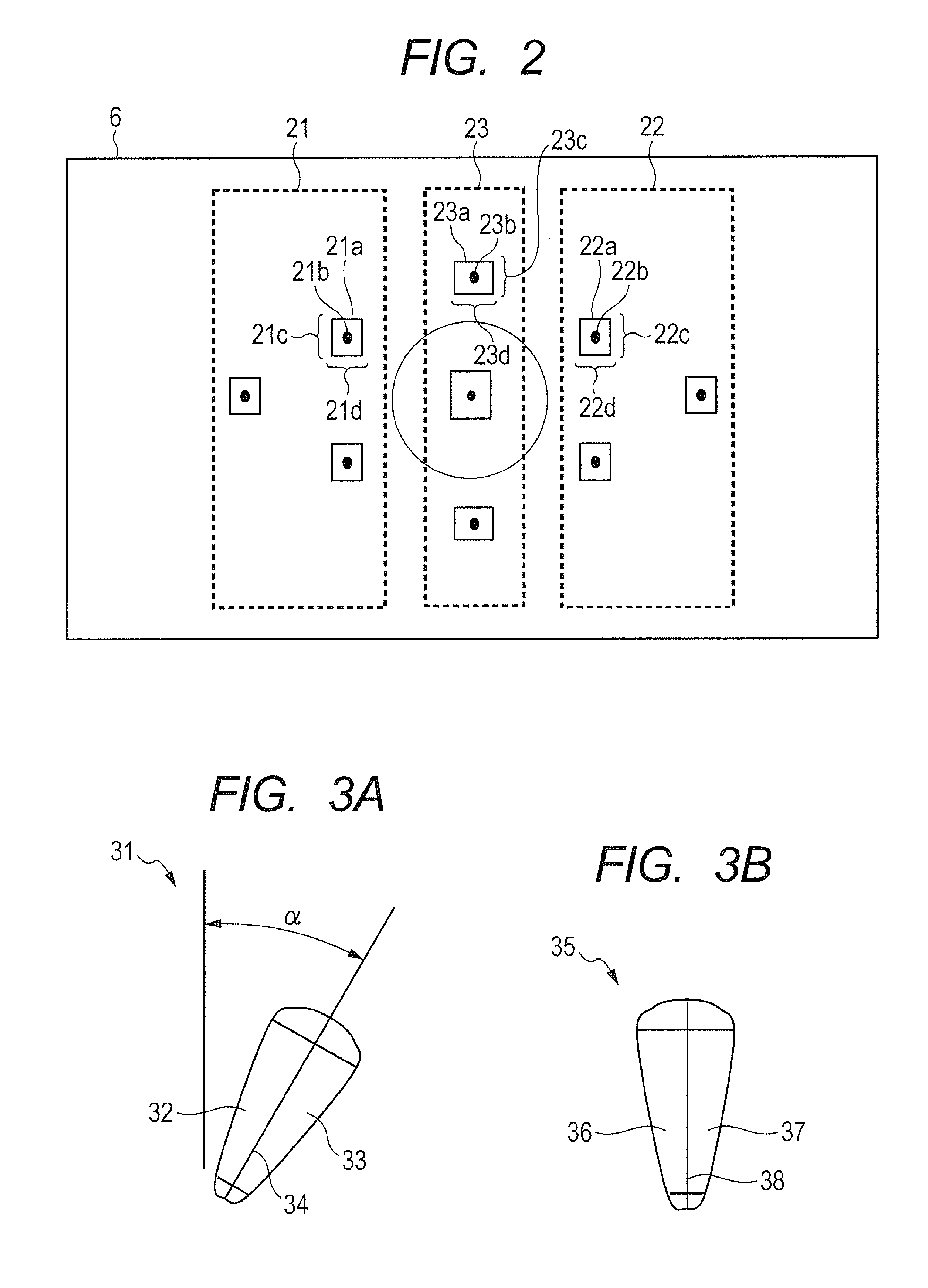
[0047]Explanation as to a configuration of the frame line 23c and the frame line 23d according to embodiment 1 of the invention will be explained. FIG. 5A is a plain view illustrating a part of four corners of the frame 23a constituted by the frame line 23c and the frame line 23d. FIG. 5B is a cross sectional view taken along a line 5B-5B of the frame line 23c.

[0048]The frame line 23d is formed by a frame line 157 of a convex portion constituted by a sloped surface 158 and a sloped surface 159 through a ridge line 160. The ridge line 160 is formed to extend in a direction orthogonal to a ridge line 38 of reflective prism 35 on a surface of optical flat plate 6.

[0049]On the other hand, the frame line 23c is formed by a frame line 151 of convex portion having a V-shaped cross section, and a convex portion 152 and a convex portion 153 formed along a contour of frame line 151. The frame line 151 of the convex portion is formed by a sloped surface 155 and a sloped surface 156 through th...

embodiment 2

[0053]The configuration of frame lines 23c and 23d according to embodiment 2 of the invention will be explained in detail. FIG. 6A is a plan view illustrating a part of four corners of frame 23a constituted by the frame lines 23c and 23d and FIG. 6B is a cross sectional view taken along a line 6B-6B of FIG. 6A. The frame line 23c is formed by a plurality of conical portions 51 and convex portions 53 and 54 having a V-shaped cross section. A plurality of conical portions 51 are formed at a certain pitch so as to be settled within the width size of the frame line 23c.

[0054]Further, the convex portions 53 and 54 are formed so as to extend within a line width (width size) of the frame line 23c at both right and left sides (both sides of line constituted by the arrangement of the conical portions 51) with respect to the conical portions 51. Furthermore, heights of the convex portions 53 and 54 are lower than those of apexes 52 of the conical portions 51 as illustrated in FIG. 6B. Theref...


PUM


Abstract

A camera comprises a display member arranged in a finder optical system. The display member is provided in a finder of the camera and is provided with a reflective prism group including a plurality of reflective prisms and a frame line formed to surround the reflective prism group. A shape forming the frame line is constituted by a convex portion, and a ridge line of the convex portion is in a twisted position with respect to a direction of a ridge line of the reflective prism.

Description

BACKGROUND OF THE INVENTION[0001]1. Field of the Invention[0002]The present invention relates to a camera having a display member.[0003]2. Description of the Related Art[0004]Conventional cameras have been provided with a finder by which an object in an imaging range is visually recognized and which has a superimposed function providing indexes showing the imaging range, a distance-measuring range and a light-measuring range. Further, in recent years, cameras to which a function for performing most suitable distance-measurement and light-measurement in accordance with situations by setting a plurality of distance-measuring and light-measuring points in a photographing view field is added have been provided. Such cameras notify a photographer the positions of indexes with displaying and non-displaying by switching emitting and non-emitting of the plurality of indexes representing the distance-measuring and light-measuring points in the finder visual field.[0005]However, the conventio...

Claims


Application Information

Patent Timeline
IPC IPC(8): G03B13/02G02B17/04
CPCG02B17/04G03B13/02G03B13/04G03B13/08
Inventor OKURA, YUKINOBUSAITO, KOSUKE
Owner CANON KK
Learn More