Object detection apparatus

a technology of object detection and object, which is applied in the direction of measuring devices, using reradiation, instruments, etc., can solve the problems of unnecessarily performing avoidance control, unnecessary performing avoidance control, and affecting the accuracy of detection results, so as to reduce the degree of confidence of the detected object position and the variation of the detected lateral position

Active Publication Date: 2016-04-28
DENSO CORP +1
View PDF8 Cites 6 Cited by
  • Summary
  • Abstract
  • Description
  • Claims
  • Application Information

AI Technical Summary

Benefits of technology

[0011]In the case of a large variation of the detected object position, despite that the detected object is actually present at a position where the detected object is less likely to interact with the moving object, it may be determined that the detected object is likely to interact with the moving object, which may cause interaction avoidance control for avoiding the interaction between the detected object and the moving object to be unnecessarily performed. As the degree of confidence of the detected object position decreases, the variation of the detected lateral position (that is the object position in the direction perpendicular to the moving direction) may be increased. Therefore, even if it is determined that the detected object is within the range of the moving object's course, it cannot be confidently determined whether or not the detected object is in a position where the detected object is likely to interact with the moving object. Addressing this concern, the above configuration can prevent the detected object that is actually at a position where the detected object is less likely to interact with the moving object from being determined as being likely to interact with the moving object.

Problems solved by technology

Thus, despite that the position of the object calculated based on the principle of triangulation is within a range of a vehicle's course, the object may be actually out of the range of the vehicle's course.
In such a case, despite that no interaction avoidance control needs to be performed, such avoidance control may be unnecessarily performed.
In the case of a large variation of the detected object position, despite that the detected object is actually present at a position where the detected object is less likely to interact with the moving object, it may be determined that the detected object is likely to interact with the moving object, which may cause interaction avoidance control for avoiding the interaction between the detected object and the moving object to be unnecessarily performed.
Therefore, even if it is determined that the detected object is within the range of the moving object's course, it cannot be confidently determined whether or not the detected object is in a position where the detected object is likely to interact with the moving object.

Method used


Image

  • Object detection apparatus
  • Object detection apparatus
  • Object detection apparatus

Examples


first embodiment

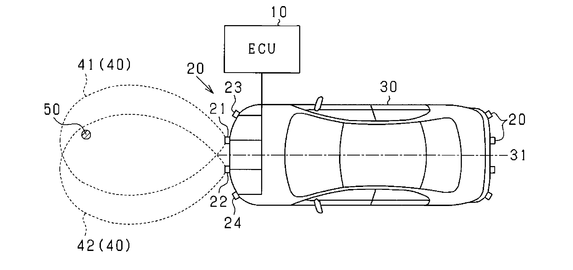
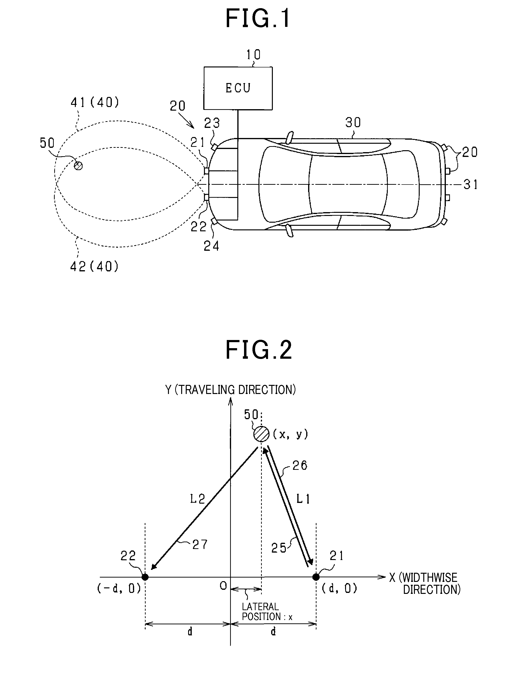
[0023]An object detection apparatus mounted in a moving object in accordance with a first embodiment of the present invention will now be explained with reference to the accompanying drawings. The object detection apparatus of the present embodiment is mounted in a vehicle as the moving object and is configured to receive object sensing information from ranging sensors mounted in the vehicle to detect an object around the vehicle, such as another vehicle, a roadway construction or the like. An object detection system in accordance with the present embodiment will now be explained with reference to FIG. 1.

[0024]Each of ranging sensors 20 may be an ultrasonic sensor having a function of transmitting an ultrasonic wave at a frequency in a range of 20-100 kHz as a probe wave and a function of receiving a reflection of the probe wave from an object. In the present embodiment, four ranging sensors 20 are attached to a front portion of the vehicle 30 (e.g., a front bumper) and spaced apart...

second embodiment

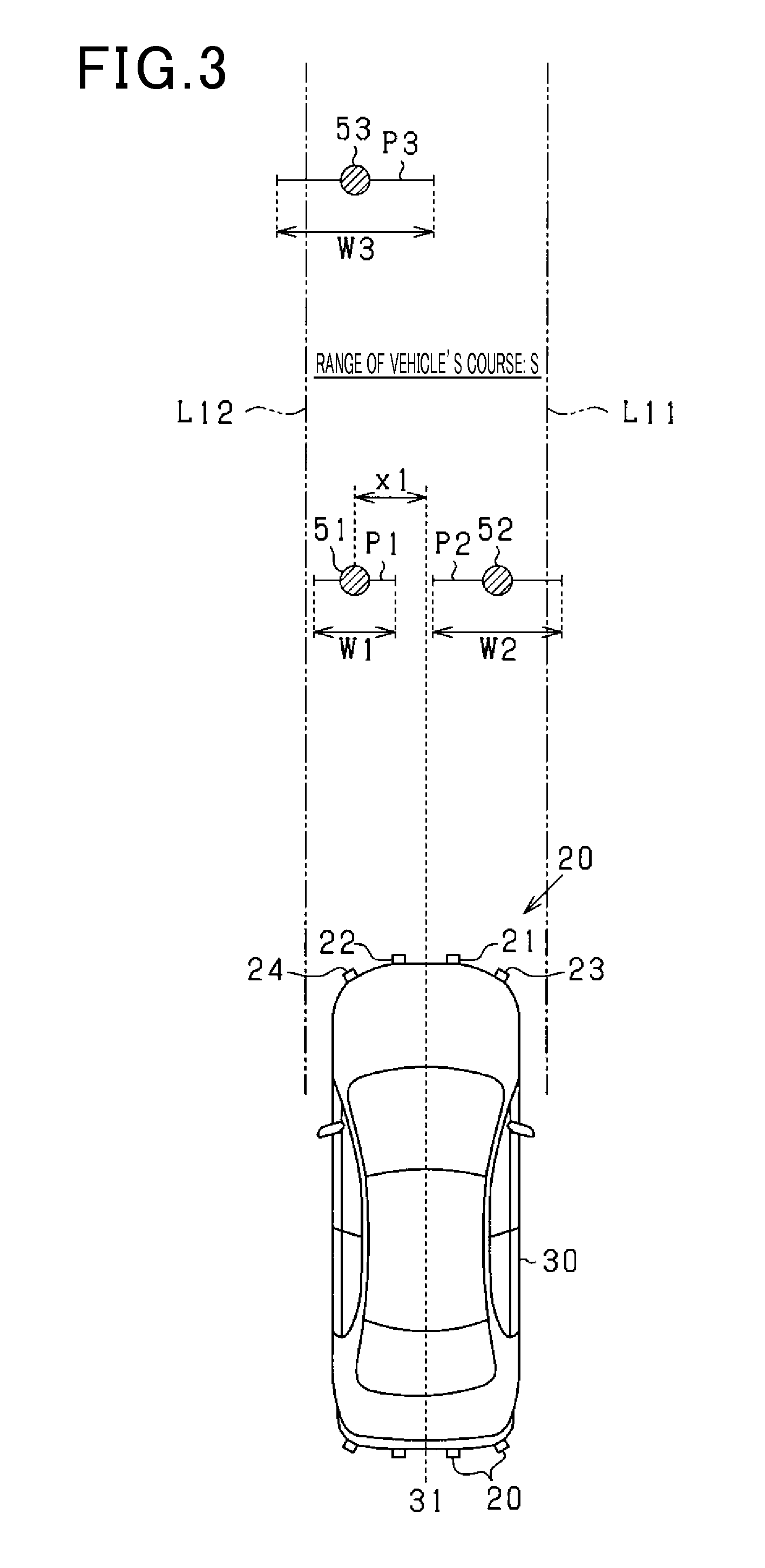
[0057]An object detection apparatus in accordance with a second embodiment of the present invention will now be explained with reference to the accompanying drawings. In the following, only differences of the second embodiment from the first embodiment will be described. In the second embodiment, a reduced range K of a vehicle's course is set by reducing the range S of the vehicle's course in the widthwise direction of the vehicle 30 to a degree of reduction as a function of the degree of confidence of the object position detected by the ranging sensors 20. Based on a positional relationship between the reduced range K of the vehicle's course and the lateral position x of the object, it is determined whether or not the object detected by the ranging sensors 20 is likely to interact with the vehicle 30.

[0058]FIG. 7 is an example where the interaction determination process is performed in accordance with the present embodiment. In FIG. 7, the double dashed lines L11, L12 respectively ...


PUM


Abstract

An object detection apparatus for detecting an object around a moving object by transmitting a probe wave and receiving reflections of the probe wave from the object via the plurality of ranging sensors. In the apparatus, an interaction determiner is configured to, if an object position calculated by a position calculator is within a range of a moving-object's course, determine whether or not the detected object is likely to interact with the moving object based on a lateral position of the detected object and a degree of confidence of the object position calculated by the position calculator. The lateral position of the detected object is the object position calculated by the position calculator in a direction perpendicular to a moving direction of the moving object.

Description

CROSS-REFERENCE TO RELATED APPLICATION[0001]This application is based on and claims the benefit of priority from earlier Japanese Patent Application No. 2014-215097 filed Oct. 22, 2014, the description of which is incorporated herein by reference.BACKGROUND[0002]1. (Technical Field)[0003]The present invention relates to an object detection apparatus for detecting an object around a moving-object carrying the apparatus.[0004]2. (Related Art)[0005]Conventionally, a known object detection apparatus, as disclosed in Japanese Patent Application Laid-Open Publication No. 2014-89077, includes at least one ranging sensor, such as an ultrasonic sensor or the like, mounted in a vehicle to detect an object, such as a pedestrian, an obstacle or the like, around the vehicle, and based on detection results, performs various types of controls, such as actuation of a braking device and notification to a driver, for improving vehicle driving safety.[0006]The object detection apparatus disclosed in J...

Claims


Application Information

Patent Timeline
Patent Type & Authority Applications(United States)
IPC IPC(8): G01S15/93G01S15/42G01S7/54G01S15/04G01S15/931
CPCG01S15/931G01S15/04G01S2015/938G01S7/54G01S15/42G01S15/46G01S15/66G01S15/878G01S2015/465
Inventor FUKUMAN, MASUMIOHBAYASHI, MOTONARIKIDA, AKIHIRO
Owner DENSO CORP
Why Eureka
Try Eureka