Cleaning nozzle assembly

Inactive Publication Date: 2016-04-28
CONET IND
View PDF6 Cites 16 Cited by
  • Summary
  • Abstract
  • Description
  • Claims
  • Application Information

AI Technical Summary

Benefits of technology

The present invention provides a cleaning nozzle assembly designed to switch between air and foreign substances to selectively provide dust suction. It also allows for adjustable suction force to prevent damage to surfaces. The assembly includes a bearing for wheels, which prevents noise and improves durability. The transfer pipe remains horizontal when in use, preventing random rotation. The main inlet includes a brush for sweeping foreign substances into the lower case. The assembly is designed to improve cleaning efficiency and convenience for users.

Problems solved by technology

Here, friction between the body and the wheels, both of which are injection molded articles, causes noise.
In addition, a typical vacuum cleaner has a problem in that when cleaning is performed using a rotary brush type suction nozzle for cleaning carpets, bedclothes, and the like, the suction nozzle can be brought into too close contact with a surface to be cleaned depending upon the kind and state of the surface, which makes it difficult to move the nozzle while causing damage to the surface.

Method used


Image

  • Cleaning nozzle assembly
  • Cleaning nozzle assembly
  • Cleaning nozzle assembly

Examples


Embodiment Construction

[0040]Hereinafter, embodiments of the present invention will be described in detail with reference to the accompanying drawings. It should be noted that the drawings are not to precise scale and may be exaggerated in thickness of lines or size of components for descriptive convenience and clarity only. In addition, terms used herein are defined by taking functions of the present invention into account and can be changed according to user or operator custom or intention. Therefore, definition of the terms should be made according to the overall disclosure set forth herein.

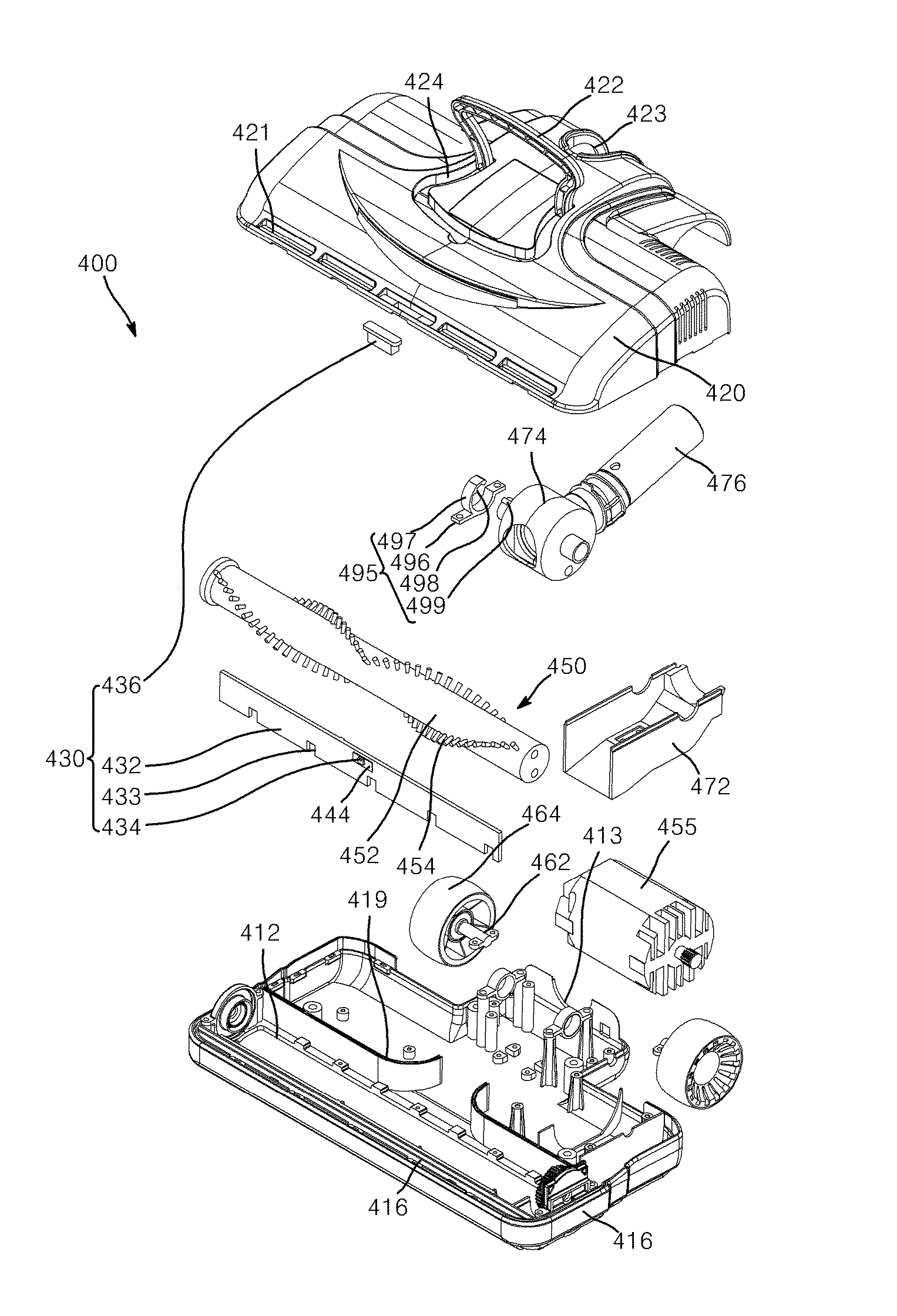
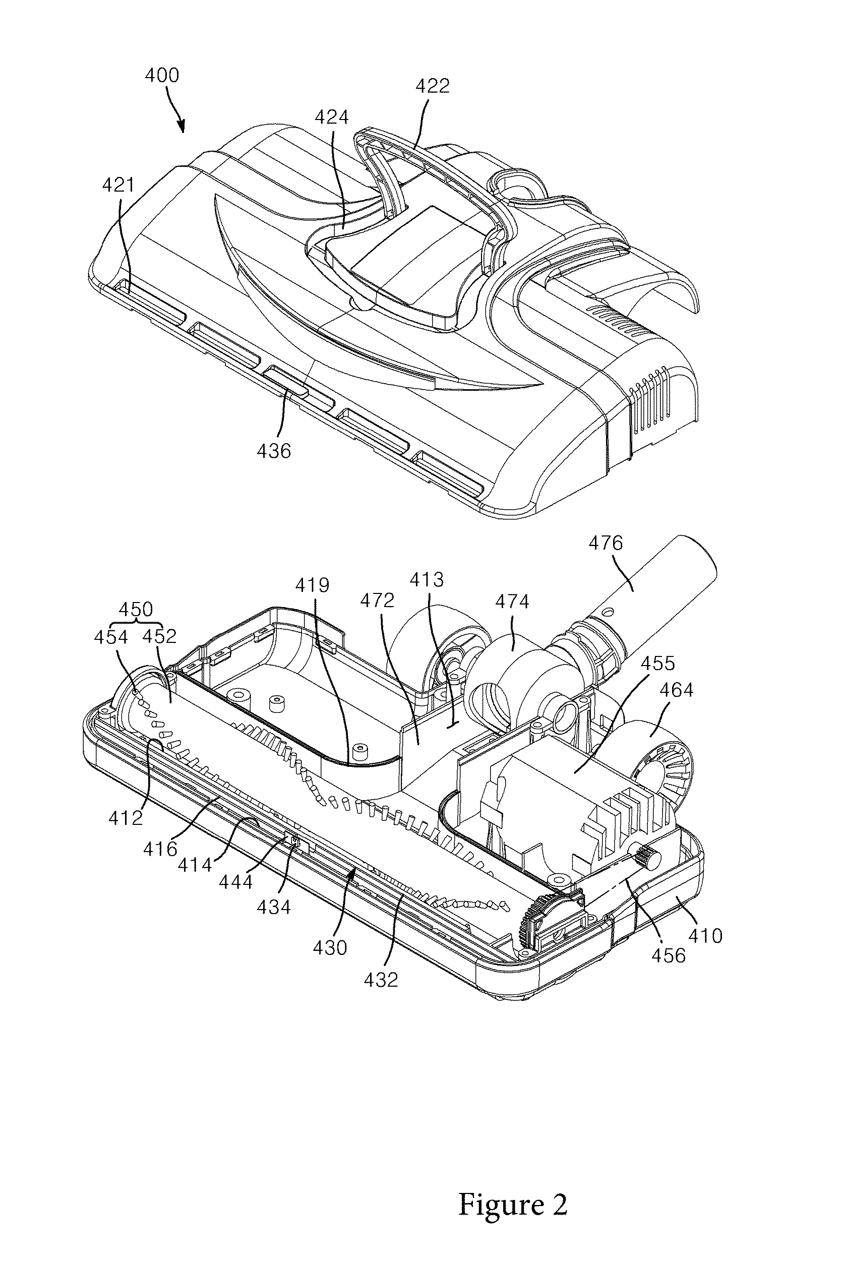
[0041]FIG. 1 is a perspective view of a vacuum cleaner including a cleaning nozzle assembly according to one embodiment of the present invention, FIG. 2 is an exploded perspective view of the cleaning nozzle assembly according to the embodiment of the present invention, and FIG. 3 is a bottom exploded perspective view of the lower case and the upper case of the cleaning nozzle assembly shown in FIG. 2.

[0042]FIG. 4 i...


PUM


Abstract

A cleaning nozzle assembly of a vacuum cleaner. The cleaning nozzle assembly includes: a lower case having a main inlet and a lower sub-inlet to guide foreign substances and air to be introduced into the lower case, wherein the lower case is open at an upper side thereof and includes a partition wall isolating the main inlet from the lower sub-inlet and having a connection hole; an upper case coupled to the lower case to cover the open upper side of the lower case; and an inflow setting unit setting inflow of foreign substances and air into the lower case through the lower sub-inlet and an upper sub-inlet by opening / closing the connection hole. The cleaning nozzle assembly can switch inlets of a cleaning nozzle receiving air and foreign substances, thereby selectively providing dust suction over a wider area and intensive dust suction, can prevent noise from being generated by wheels of the cleaning nozzle, and allows the cleaning nozzle to remain horizontal with respect to a floor when a transfer pipe provided to the cleaning nozzle for changing a cleaning location during cleaning is lifted up.

Description

BACKGROUND[0001]1. Technical Field[0002]The present invention relates to a cleaning nozzle assembly. More particularly, the present invention relates to a cleaning nozzle assembly which can switch inlets of a cleaning nozzle receiving air and foreign substances, thereby selectively providing dust suction over a wider area and intensive dust suction, prevent a noise generated by wheels of the cleaning nozzle, and allow the cleaning nozzle to remain horizontal with respect to a floor when a transfer pipe provided to the cleaning nozzle for changing a cleaning location during cleaning is lifted up.[0003]2. Description of the Related Art[0004]A typical vacuum cleaner has a structure wherein a motor for generating vacuum and an envelope type filter are disposed within a main body of the cleaner to allow sludge to be introduced into the main body of the cleaner through vacuum force generated by activation of the motor and to be filtered out through the filter, such that filth having been ...

Claims


Application Information

Patent Timeline
IPC IPC(8): A47L9/04A46B9/02
CPCA46B9/02A47L9/04A47L5/28A47L9/0054A47L9/0081A47L9/0411
Inventor SONG, SUNG WOOK
Owner CONET IND
Why Eureka
Try Eureka