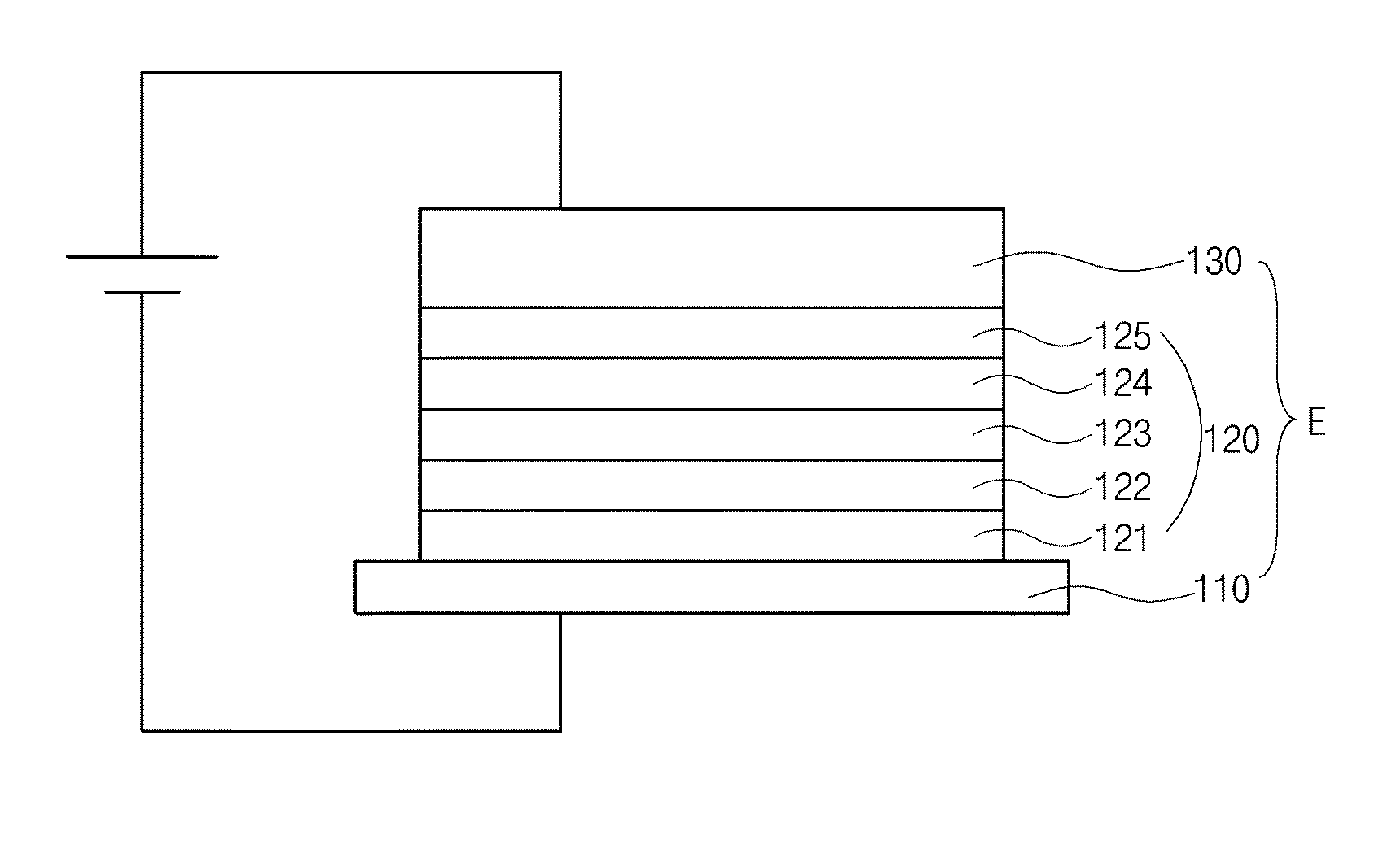
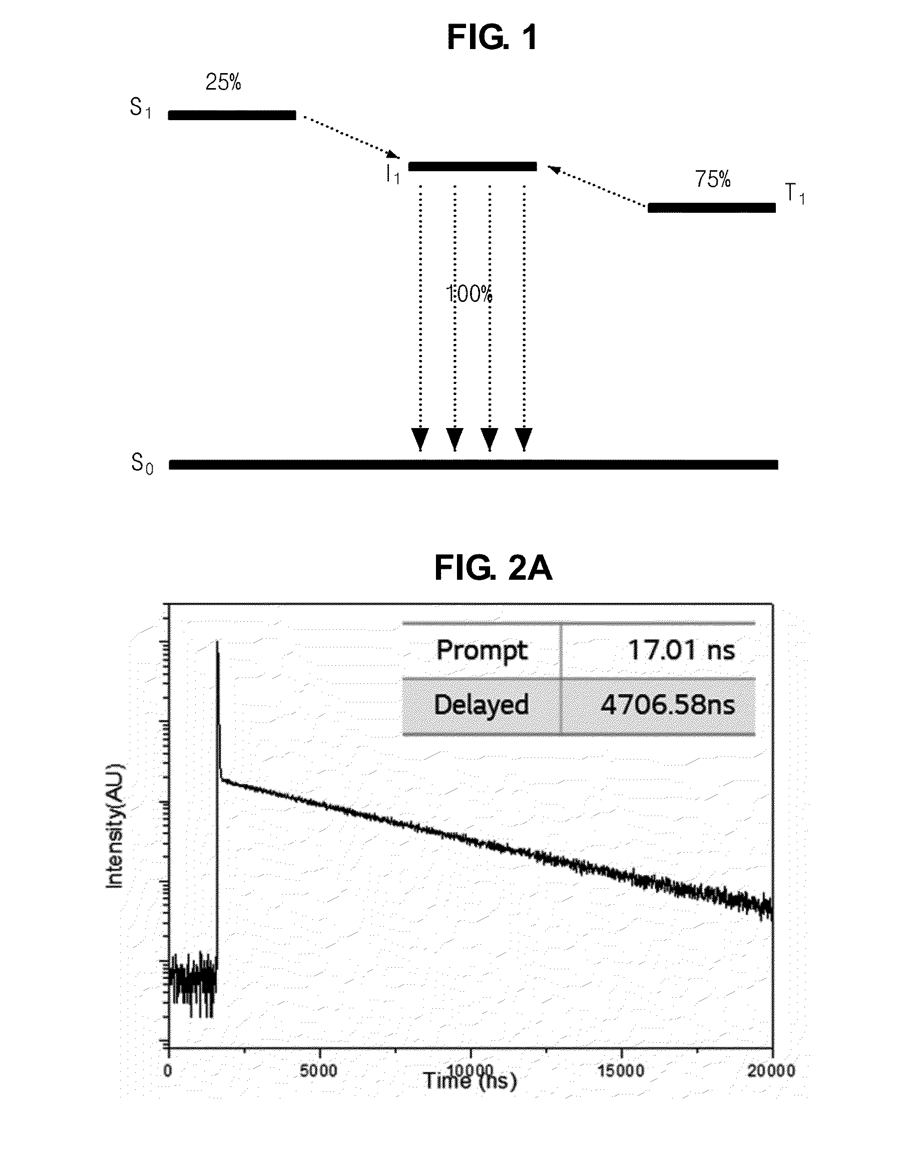
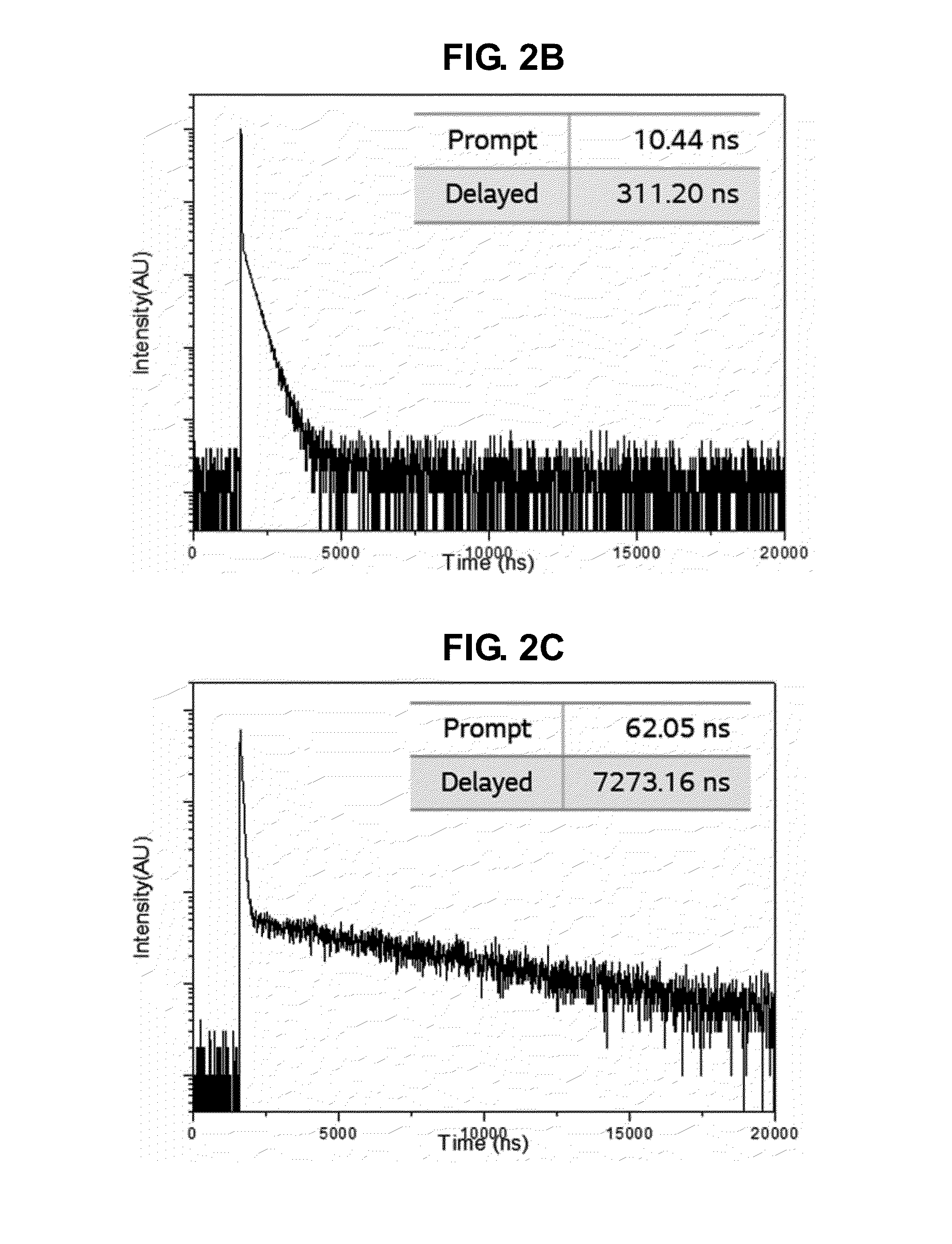
Delayed fluorescence compound, and organic light emitting diode and display device using the same
a technology of fluorescence compound and display device, which is applied in the direction of luminescent composition, organic chemistry, thermoelectric devices, etc., can solve the problems of not meeting the requirements of emitting efficiency and reliability, and achieves improved emission efficiency, delayed fluorescence, and high emitting efficiency
Active Publication Date: 2016-04-21
LG DISPLAY CO LTD
View PDF2 Cites 3 Cited by
- Summary
- Abstract
- Description
- Claims
- Application Information
AI Technical Summary
Benefits of technology
The invention provides a compound that emits light quickly and efficiently. This compound can be used in OLED displays and other lighting devices, making them more efficient and effective.
Problems solved by technology
However, there is no blue phosphorescent compound meeting the requirements in emitting efficiency and reliability.
Method used
View moreImage
Smart ImageViewing Examples
Examples
Login to View More PUM
 Abstract
Discussed is a delayed fluorescence compound including a first electron donor moiety of indolo-[3,2,1-j,k]carbazole; a second electron donor moiety selected from indolo-[3,2,1-j,k]carbazole, carbazole, or triphenylamine; and an electron acceptor moiety selected from dibenzothiophene sulfone or diphenyl sulfone, wherein the first and second electron donor moieties are combined to the electron acceptor moiety, and the electron acceptor moiety is combined to a third position or a sixth position of the first electron donor moiety.
Description
CROSS-REFERENCE TO RELATED APPLICATIONS[0001]This application claims priority to and the benefit of Republic of Korea Patent Application No. 10-2014-0140972 filed on Oct. 17, 2014, Republic of Korea Patent Application No. 10-2014-0140973 filed on Oct. 17, 2014, Republic of Korea Patent Application No. 10-2015-0130520 filed on Sep. 15, 2015, and Republic of Korea Patent Application No. 10-2015-0130917 filed on September 16, 2015, all of which are hereby incorporated by reference in their entirety.BACKGROUND OF THE INVENTION[0002]1. Field Of The Invention[0003]Embodiments of the invention relate to an organic light emitting diode (OLED) and more particularly to a delayed fluorescence compound having excellent emitting efficiency and an OLED and a display device using the delayed fluorescence compound.[0004]2. Discussion Of The Related Art[0005]The requirements of the large-size display device have led to developments in flat panel display devices as an image displaying device. Among t...
Claims
Login to View More Application Information
Patent Timeline
 IPC IPC(8): H01L51/00C09K11/06C07D487/06H01L51/50H01L51/52
CPCH01L51/0072C09K2211/1092H01L51/5237C07D487/06C09K11/06H01L51/0074H01L51/0061H01L51/5012H01L51/5056H01L51/5072H01L51/5088H01L51/5092C09K2211/1029C09K2211/1014H01L51/5004C07D519/00H10K85/6576H10K85/6572H10K50/11H10K50/17H10K50/84C07D487/04H10K85/631H10K85/636H10K50/15H10K50/16H10K50/171H10K2101/40
Inventor YANG, JOONG-HWANYOON, KYUNG-JINNOH, HYO-JINYOON, DAE-WISHIN, IN-AEKIM, JUN-YUN
Owner LG DISPLAY CO LTD
Features
- Generate Ideas
- Intellectual Property
- Life Sciences
- Materials
- Tech Scout
- Unparalleled Data Quality
- Higher Quality Content
- 60% Fewer Hallucinations
Learn More Browse by: Latest US Patents, China's latest patents, Technical Efficacy Thesaurus, Application Domain, Technology Topic, Popular Technical Reports.
© 2025 PatSnap. All rights reserved.Legal|Privacy policy|Modern Slavery Act Transparency Statement|Sitemap|About US| Contact US: help@patsnap.com


