
Structural testing of integrated circuits

a technology of integrated circuits and structural testing, applied in the direction of electronic circuit testing, measurement devices, instruments, etc., can solve the problems of ic to function incorrectly, scan cells and faults in the ic increase, ate has a limited memory and a restricted speed

Inactive Publication Date: 2016-04-21
NXP USA INC
View PDF10 Cites 4 Cited by
  • Summary
  • Abstract
  • Description
  • Claims
  • Application Information

AI Technical Summary

Benefits of technology

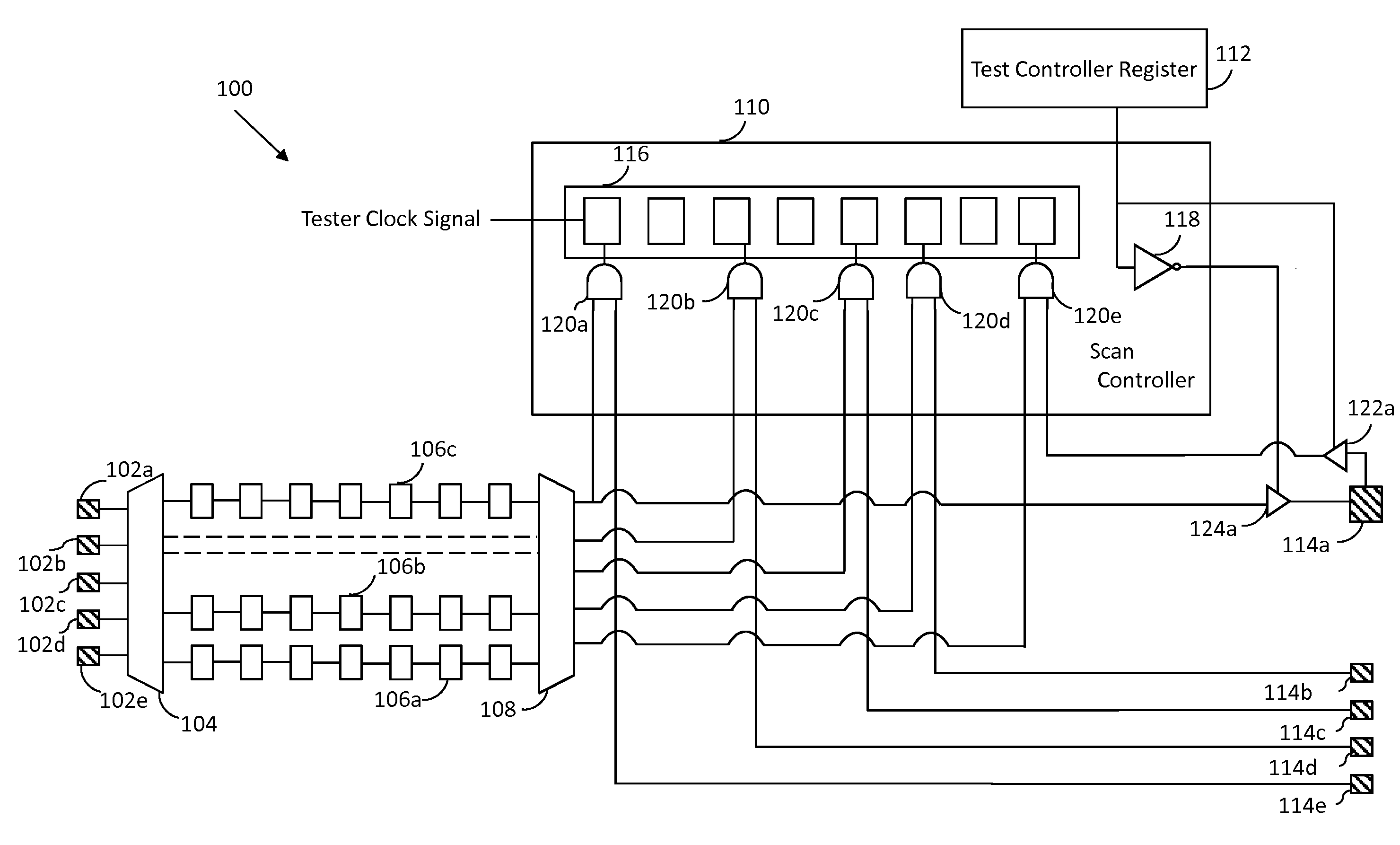
The present invention aims to provide an improved method for testing integrated circuits using built-in self-tests (BIST) and test compression. The invention addresses the limitations of current testing techniques, such as limited memory and speed restrictions, and the need for large volumes of test data. The invention allows for quick and efficient testing of ICs in the field and does not require large volumes of test data. The technical effects of the invention include reducing test pattern scan out time, improving fault coverage, and avoiding corruption of test patterns with unknown values.

Problems solved by technology

Such ICs may contain manufacturing defects caused by, for example, dust particle contamination during fabrication, which can cause the IC to function incorrectly.
With an increase in the digital components in the IC, the scan cells and faults in the IC increase.
However, the ATE has a limited memory and a restricted speed, as well as a fixed number of input / output (IO) pads.
Further, as the scan-in pads, scan cells, and scan-out pads function synchronously, shift speeds thereof are limited by the shift speed of the scan-out pads as the shift speed of the scan-out pads is the slowest shift speed among these elements.
Thus, the test time increases, thereby increasing manufacturing costs.
However, the pseudo-random test patterns applied used during BIST do not provide sufficient fault coverage in a limited time period to locate “hard to detect” faults.
Further, BIST does not provide a method to avoid the corruption of the signature with non-deterministic values (also referred to as ‘unknown values’ or ‘X values’).

Method used


Image

  • Structural testing of integrated circuits
  • Structural testing of integrated circuits
  • Structural testing of integrated circuits

Examples


Embodiment Construction

[0015]The detailed description of the appended drawings is intended as a description of the currently preferred embodiments of the present invention, and is not intended to represent the only form in which the present invention may be practiced. It is to be understood that the same or equivalent functions may be accomplished by different embodiments that are intended to be encompassed within the spirit and scope of the present invention.

[0016]In an embodiment of the present invention, an integrated circuit operable in scan test and functional modes when connected to an automated test equipment (ATE) for testing the integrated circuit is provided. The integrated circuit includes first and second sets of input / output (IO) pads, a decompressor, a plurality of scan chains, a compressor, and a scan controller. The first set of IO pads is connected to the ATE for receiving a plurality of test patterns when the integrated circuit is in the scan test mode. The decompressor is connected to t...


PUM


Abstract

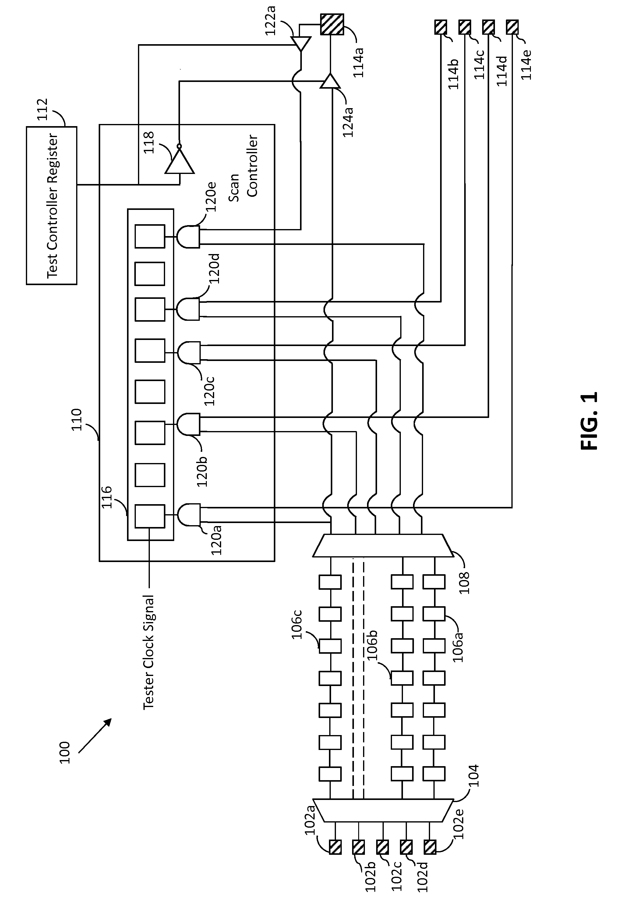
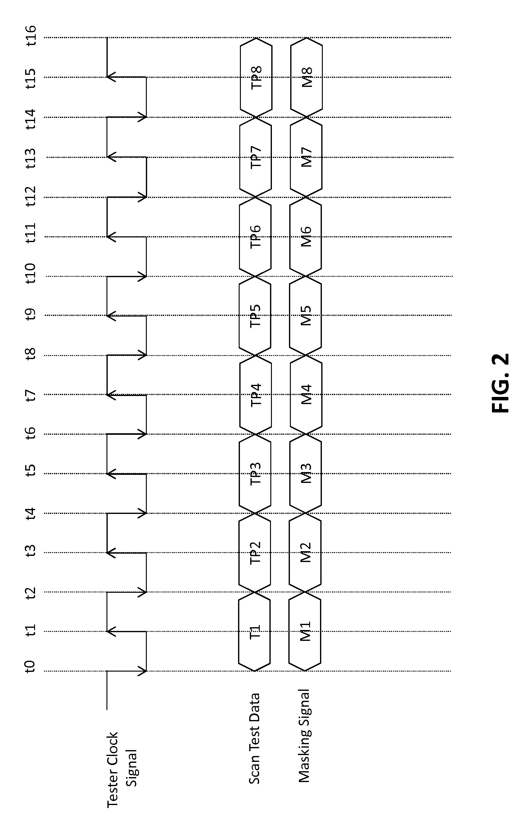
An integrated circuit (IC) that is operable in scan test and functional modes includes scan-in pads, scan-out pads, scan chains, a compressor, a decompressor, a test control register, and a scan controller. The scan controller includes a multiple input shift register (MISR), an inverter, and multiple logic gates. The scan-in and scan-out pads receive scan test data and masking signals, respectively. The decompressor provides decompressed scan test data to the scan chains, which generate functional responses based on the decompressed scan test data. The compressor provides compressed functional responses to the scan controller. The logic gates receive the compressed functional responses and the masking signals from the compressor and the corresponding scan-out pads, respectively, and generate corresponding masked signals. The masking signals mask non-deterministic values in the decompressed functional responses. The MISR receives the masked signals and generates an error free signature.

Description

BACKGROUND OF THE INVENTION[0001]The present invention relates generally to integrated circuits, and, more particularly, to structural testing of integrated circuits.[0002]Integrated circuits (ICs) integrate various analog and digital components on a single chip. Such ICs may contain manufacturing defects caused by, for example, dust particle contamination during fabrication, which can cause the IC to function incorrectly. Thus, testing ICs to detect manufacturing defects is essential. Design for test (DFT) is a technique that adds testability features to an IC to identify manufacturing defects. DFT enables an automatic-test-equipment (ATE) to execute various fault tests on the IC. The ATE uses test patterns generated by test pattern generators, such as automatic test pattern generators (ATPG), pseudo-random pattern generators (PRPG), and the like, to detect faults in ICs.[0003]DFT automates the detection of design faults and hence reduces the cost and time required for development ...

Claims


Application Information

Patent Timeline
Patent Type & Authority Applications(United States)
IPC IPC(8): G01R31/3177
CPCG01R31/3177G01R31/31908G01R31/3172G01R31/318572
Inventor JINDAL, ANURAGMAHAJAN, NIPUN
Owner NXP USA INC
Learn More