
Mobile device mounting and charging system

a technology for charging systems and mobile devices, applied in fixed connections, coupling device connections, transportation and packaging, etc., can solve the problems of slow charging vs. our direct contact, reliable with multiple components, and low efficiency, so as to make driving safer, secure the phone on the dash, and keep one hand on the steering wheel

Inactive Publication Date: 2016-04-14
AIBC INT
View PDF8 Cites 30 Cited by
  • Summary
  • Abstract
  • Description
  • Claims
  • Application Information

AI Technical Summary

Benefits of technology

This invention allows for easier charging and securing of mobile devices in vehicles while driving. It achieves this by avoiding the need for multiple steps and a two-handed operation. Additionally, it can be embedded in a wall for out-of-vehicle use. This invention also makes driving safer as it helps minimize the need for customers to hold their phones while driving and keeps them within easy reach while driving.

Problems solved by technology

The disadvantages of wireless charging systems are significant compared with our invention:1. Low efficiency and slower charging vs. our direct contact.2. More expensive vs. lower cost.3. Less reliable with multiple components vs. simple structure, less parts.4. Bigger size of base vs. smaller size of base, this will allow applications with limited space.5. Horizontal position only vs. vertical & horizontal, the base can be embedded on the wall and mobile device can be mounted vertically and charging.

Method used


Image

  • Mobile device mounting and charging system
  • Mobile device mounting and charging system
  • Mobile device mounting and charging system

Examples


Embodiment Construction

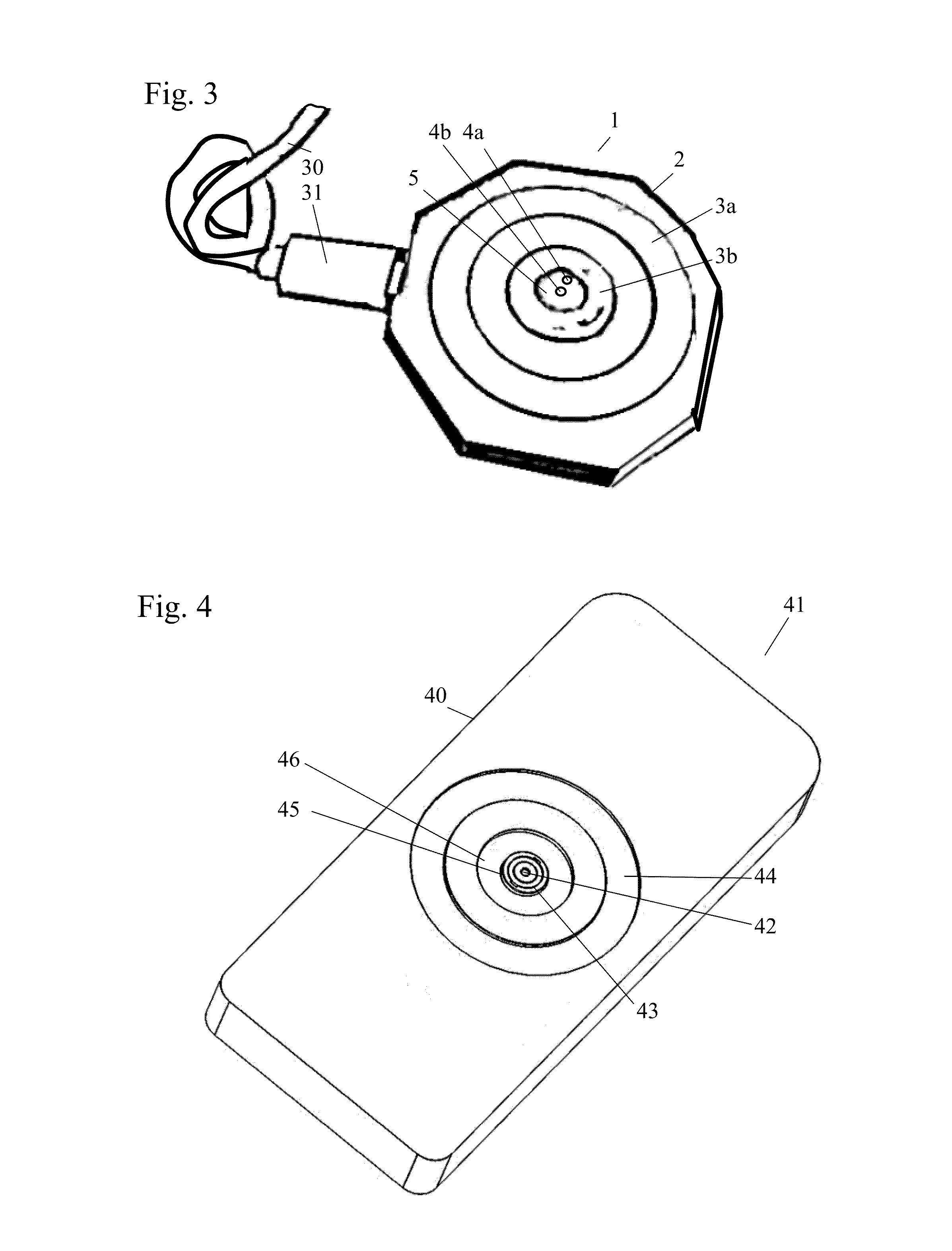
[0034]Referring to FIGS. 1-12, the major parts of the system of the invention are a magnetic charging base 1 and a mobile device case 41.

[0035]The invention provides a compact solution integrated with a mobile device case 41 allowing a user to attach their phone or other mobile device 90 to the device case 41 and dock it to the charging base 1 with one hand-motion. The device case 41 is held on the charging base 1 through magnetic force between magnets 3a and 3b in the base 1 and magnetic material plates 44 and 46 in the case 41.

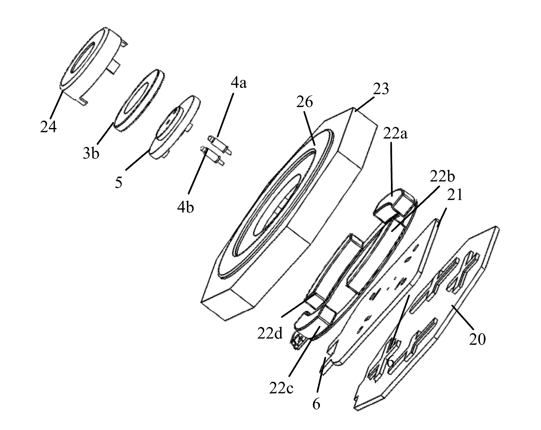
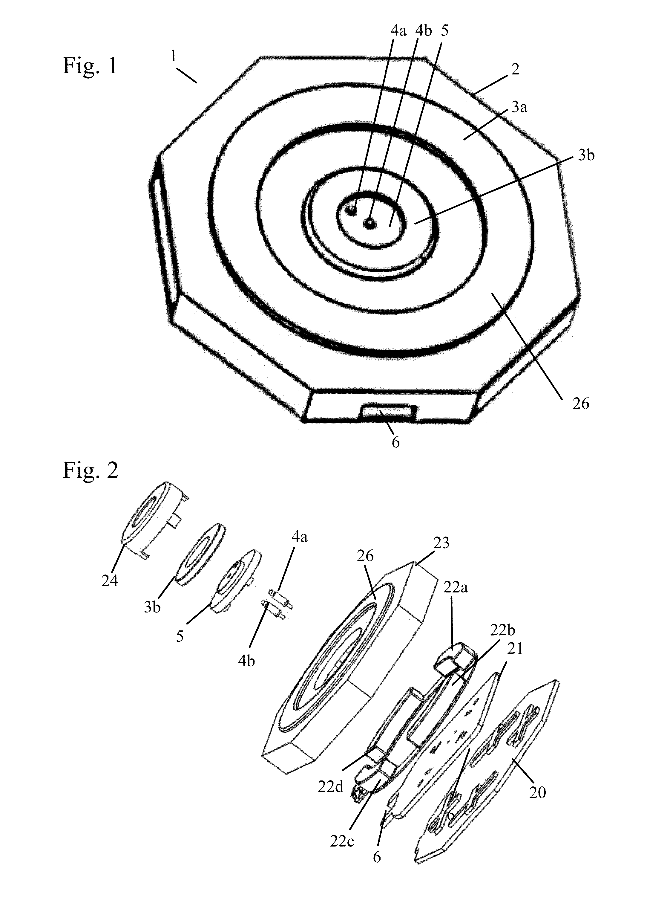
[0036]FIG. 1 shows a front view of the charging base, and FIG. 2 shows an exploded view. The charging base has a body 2 made up of a front cover 23 and a back cover 20 encasing all of the components of the charging base. The front cover 23 has a circular surface ring 26 for centering the mobile device case 41, as will be explained below. A printed circuit board (PCB) 21 is mounted inside the body 2.

[0037]As can be seen in these figures, a number of magnets—i...


PUM


Abstract

A mobile device mounting and charging system having a device case with female connection points on the back of the mobile device case connected to the device through charging connections. A charging base has male contacts for mating with the female connection points, preferably in the form of pogo pins, with a magnet that maintains base and case connection. The charging base is connected to a power source.

Description

REFERENCE TO RELATED APPLICATIONS[0001]This application claims one or more inventions which were disclosed in Provisional Application No. 62 / 062,278, filed Oct. 10, 2014, entitled “Mobile device mounting and charging system”. The benefit under 35 USC §119(e) of the U.S. provisional application is hereby claimed, and the aforementioned application is hereby incorporated herein by reference.BACKGROUND OF THE INVENTION[0002]1. Field of the Invention[0003]The invention pertains to the field of mounting and charging systems. More particularly, the invention pertains to mounting and charging systems for portable devices such as mobile phones or the like.[0004]2. Description of Related Art[0005]With prior art mounts, a user accomplishes charging by finding a cable and plugging in their device—cell phone, GPS, MP3 player—every time they are in their vehicle. These mounts hold phones with clamp-style devices that require two hands and multiple actions. Apple's Lightning® or 30-pin connectors...

Claims


Application Information

Patent Timeline
IPC IPC(8): H02J7/00
CPCH02J7/0052H02J7/0044H01R12/57H01R13/2421H01R13/6205
Inventor CUI, YANG
Owner AIBC INT
Learn More