
Dental cleaning apparatus

a technology for cleaning equipment and teeth, applied in the field of dental cleaning equipment, can solve the problems of less availability of dental equipment for home use, complex apparatus, and high cost of dental professionals, and achieve the effect of improving oral health

Inactive Publication Date: 2016-04-14
UNGAR DALE
View PDF5 Cites 85 Cited by
  • Summary
  • Abstract
  • Description
  • Claims
  • Application Information

AI Technical Summary

Benefits of technology

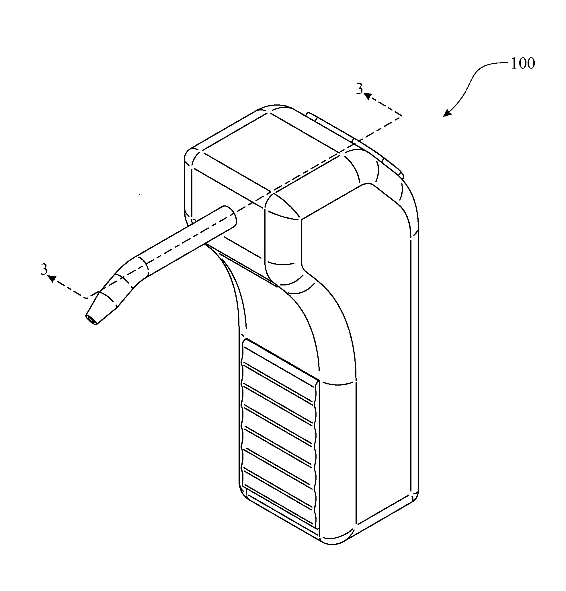
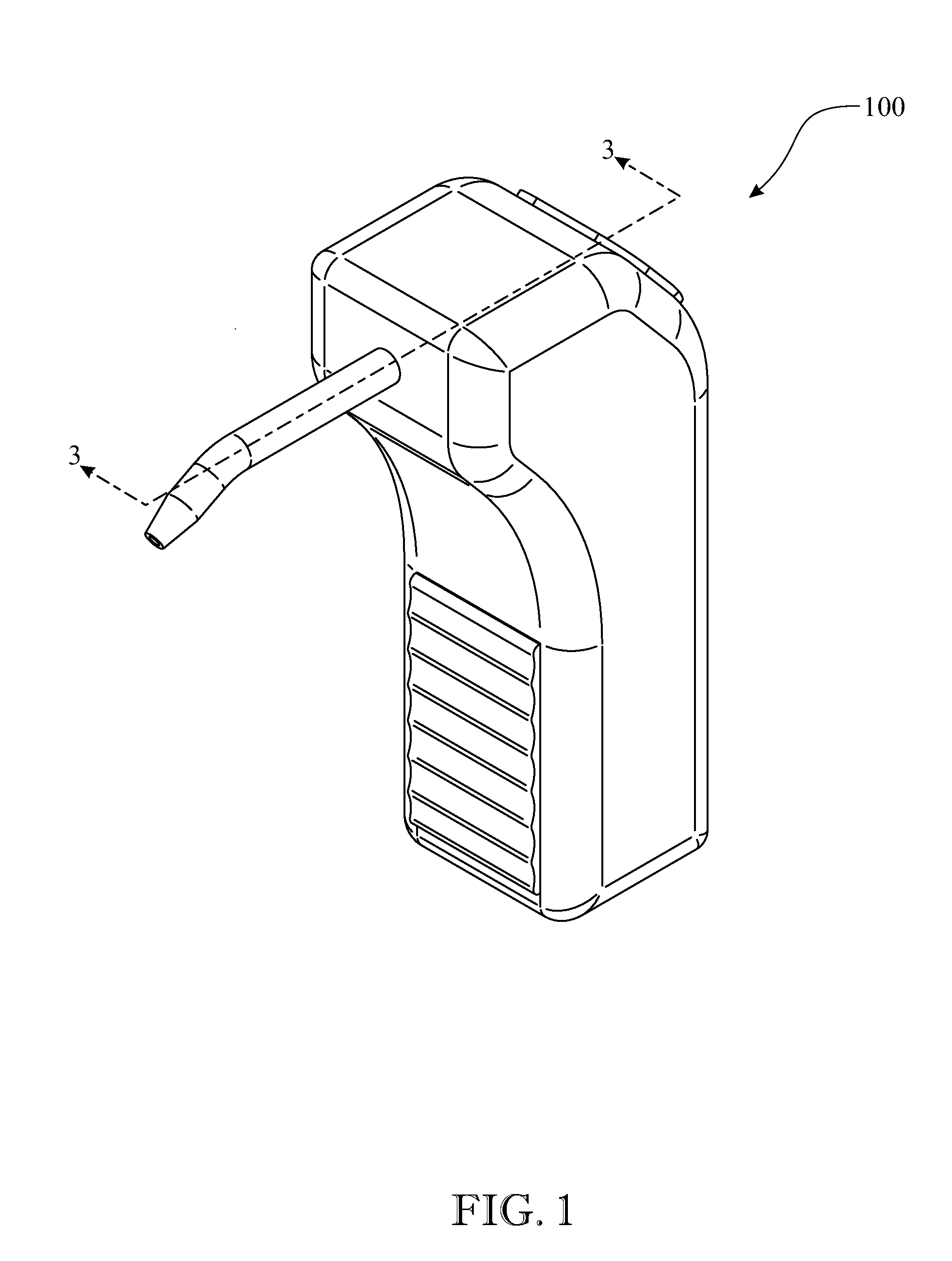
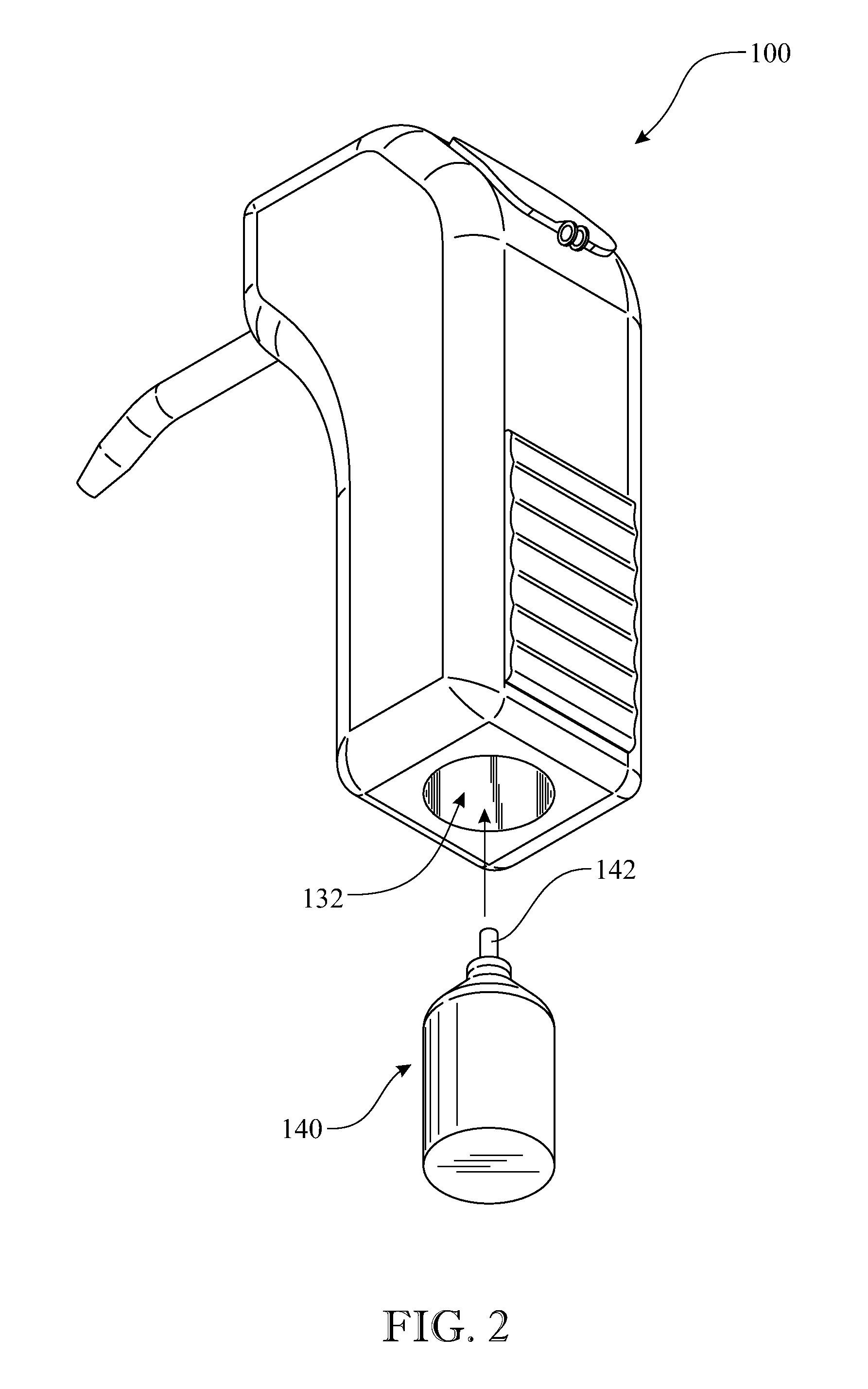
The dental cleaning apparatus described in this patent connects a pressurized air cartridge to a cleaning composition container through an actuator mechanism. The actuator mechanism is selectively activated to controllably actuate the pressurized air and enable fluid communication between them. This causes the cleaning composition to flow from the container to the nozzle assembly, resulting in a pressurized flow of the cleaning composition. The dental cleaning apparatus is designed to improve oral health by effectively cleaning dental plaque and debris.

Problems solved by technology

Conventionally, such devices are expensive and available to dental professionals such as dentists and dental hygienists.
However, this apparatus is complex, expensive and relies upon the use of an external pressurization source as well as an external abrasive powder and water source.
Such devices for home use are less available, primarily due to their complexity and high cost.
The need for technical expertise and external power sources limits the use of such dental appliances outside of a professional dental environment, such as in a home environment.
Moreover, conventional dental appliances are very expensive, and lack sufficient storage capacity to contain an adequate volume of an abrasive composition, such as dry powder, to perform a complete cleaning procedure or to prepare a tooth surface during a dental restoration process.
Again, this requirement hinders home use applications.

Method used


Image

  • Dental cleaning apparatus
  • Dental cleaning apparatus
  • Dental cleaning apparatus

Examples


Embodiment Construction

[0053]The following detailed description is merely exemplary in nature and is not intended to limit the described embodiments or the application and uses of the described embodiments. As used herein, the word “exemplary” or “illustrative” means “serving as an example, instance, or illustration.” Any implementation described herein as “exemplary” or “illustrative” is not necessarily to be construed as preferred or advantageous over other implementations. All of the implementations described below are exemplary implementations provided to enable persons skilled in the art to make or use the embodiments of the disclosure and are not intended to limit the scope of the disclosure, which is defined by the claims. For purposes of description herein, the terms “upper”, “lower”, “left”, “rear”, “right”, “front”, “vertical”, “horizontal”, and derivatives thereof shall be used to describe the invention in accordance with their common meaning. Furthermore, there is no intention to be bound by a...


PUM


Abstract

A dental cleaning apparatus is configured as a hand-held unit. The appliance includes a housing body having an interior housing cavity. The housing cavity includes an upper compartment configured to receive a volume of cleaning composition within or in absence of a container. The container may be permanently fixed in the interior housing cavity of the housing body or may be removable and replaceable through an uncoverable side opening in the housing body The housing cavity also includes a lower compartment configured to receive a pressurized air canister. An elongated hollow nozzle assembly is mounted to an upper end section of the housing body and has a nozzle conduit providing fluid communication between the cleaning composition and a tip section of the hollow nozzle assembly.

Description

CROSS REFERENCE(S) TO RELATED APPLICATION(S)[0001]This U.S. non-provisional patent application claims the benefit of co-pending U.S. provisional patent application No. 62 / 063,511, filed Oct. 14, 2014, which is incorporated by reference herein in its entirety.FIELD OF THE INVENTION[0002]The present invention relates to dental cleaning devices. More particularly, the invention pertains to portable handheld apparatus adapted to discharge a contained pressurized stream of an abrasive composition for cleaning an exterior surface of teeth.BACKGROUND OF THE INVENTION[0003]A variety of dental devices are known for cleaning, polishing and otherwise treating an exterior surface of a tooth. For example, air polishing is a procedure that uses air and water pressure to deliver a controlled stream of specially processed sodium bicarbonate or glycine powders in the form of slurry through a device nozzle. Fine particles of powders are propelled by compressed air in a warm spray and directed onto th...

Claims


Application Information

Patent Timeline
IPC IPC(8): A61C17/02
CPCA61C17/0205A61C17/02A61C17/0202
Inventor UNGAR, DALE
Owner UNGAR DALE
Learn More