
Waterless Toilet System And Method With Ventilation Control

a waterless toilet and ventilation control technology, applied in water installations, construction, domestic applications, etc., can solve the problems of poor or difficult access to collection or composting tanks below the commode, unsuitable use of potable water, and poor or difficult cleaning, so as to reduce or eliminate odors, the effect of removing was

Active Publication Date: 2016-04-14
CONVERGENT MARKET RESEACH INC
View PDF3 Cites 0 Cited by
  • Summary
  • Abstract
  • Description
  • Claims
  • Application Information

AI Technical Summary

Benefits of technology

The present invention is a toilet system that does not require water to remove waste and provides ventilation to reduce or eliminate odors in the toilet room. It includes a transport conduit, flush member, outer seal element with ventilation passages, and actuator system. The system is installed on a support structure and a holding tank is located on the opposite side of the toilet room wall with a ventilation stack and fan to induce airflow through the system. The flush member and actuator system work together to move excreta to the holding tank for processing, while the outer seal element and actuator system work together to create a seal between the discharge conduit and holding tank and to break the seal only temporarily to allow excreta to be discharged from the transport conduit to the holding tank. The ventilation passages facilitate ventilation from the interior of the transport conduit to the holding tank and reduce or eliminate odors that might otherwise escape from the toilet system to the toilet room.

Problems solved by technology

However, even where a water supply is available, it may be undesirable to use potable water to remove and transport waste in toilet and sanitation systems.
This prior art arrangement requires significant excavation for ground floor commodes.
Collection or composting tanks below the commode also have poor or difficult access for clean out.
Other waterless toilet systems rely on complex vacuum systems and / or mechanical systems and are not suited for many applications in which waterless toilets could be advantageous.

Method used


Image

  • Waterless Toilet System And Method With Ventilation Control
  • Waterless Toilet System And Method With Ventilation Control
  • Waterless Toilet System And Method With Ventilation Control

Examples


Embodiment Construction

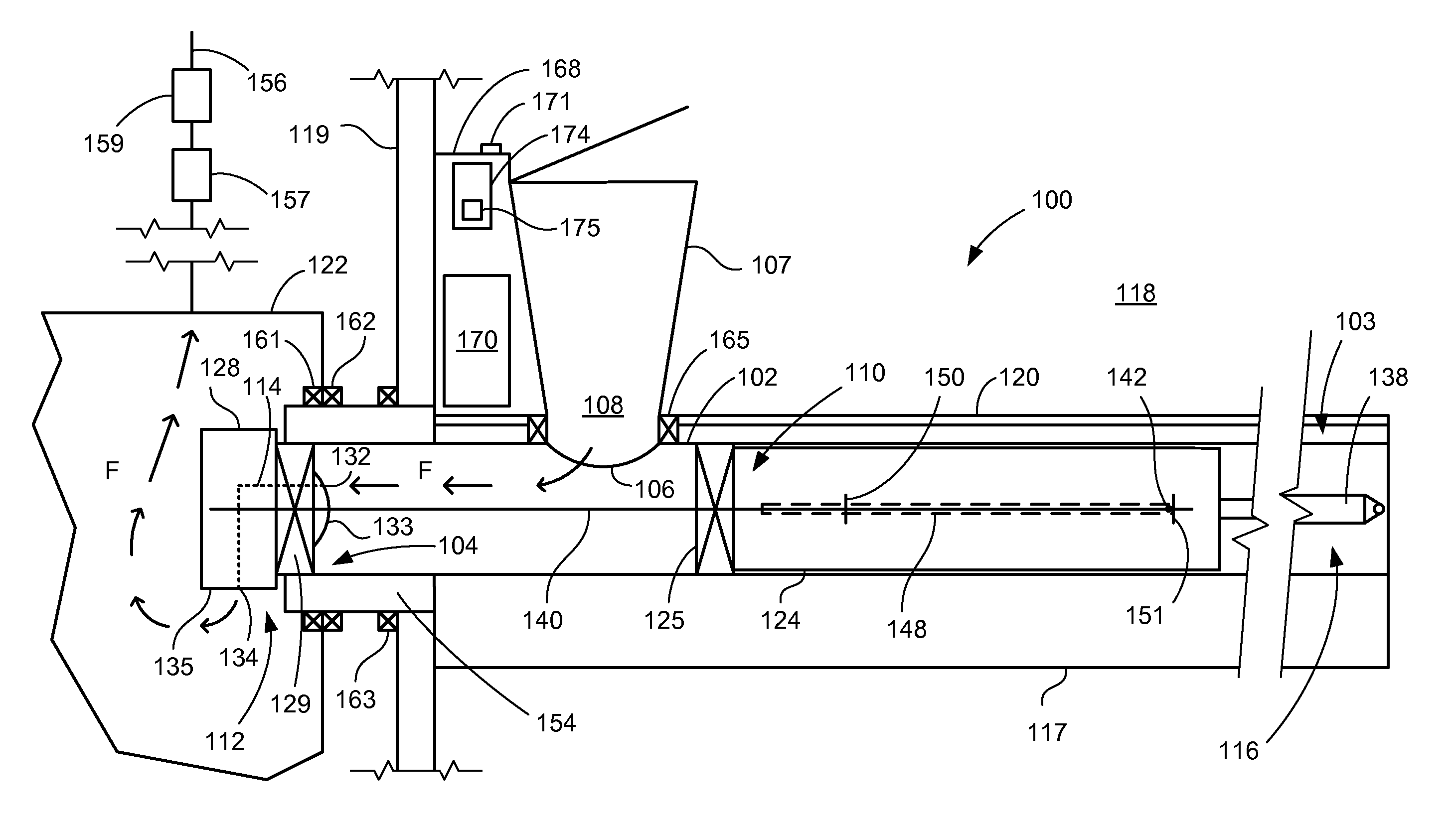
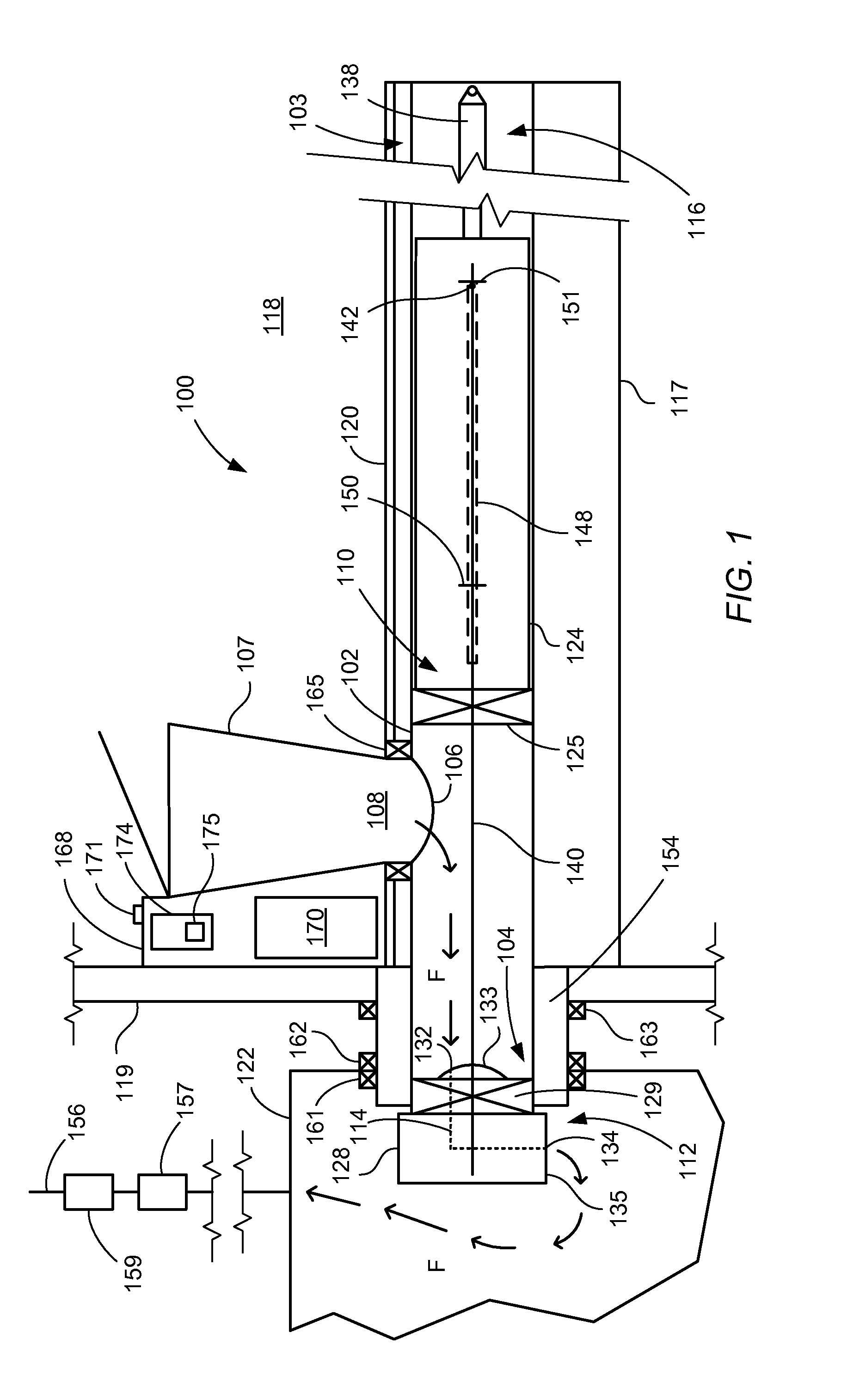
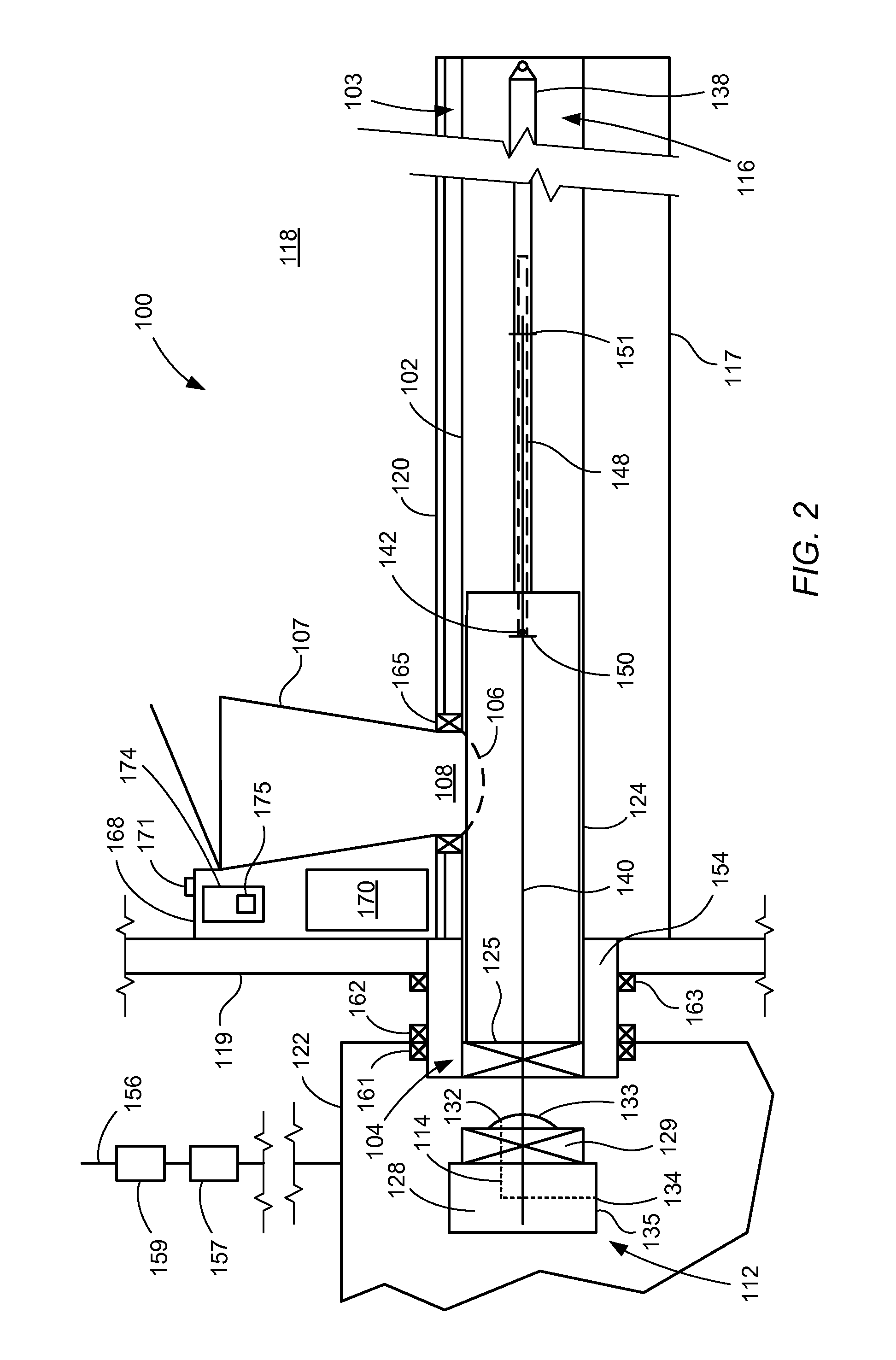
[0019]The following disclosure will describe a toilet system within the scope of the present invention with reference to a first embodiment illustrated in FIGS. 1-3. FIGS. 1-3 will also be used to describe the operation of the illustrated toilet system through the flush cycle. FIGS. 4-7 will be used to describe additional details and features which may be incorporated in a toilet system within the scope of the present invention.

[0020]Referring particularly to FIGS. 1 and 2, a toilet system 100 embodying principles of the invention includes a transport conduit 102 which extends essentially horizontally in the orientation of the figures from an inner end shown at reference numeral 103 to a discharge end shown generally at reference numeral 104. Transport conduit 102 includes a commode opening 106 located between inner end 103 and discharge end 104. A commode 107 is located above commode opening 106 with a lower opening 108 generally aligned with the commode opening. Toilet system 100 ...


PUM


Abstract

A toilet system includes a transport conduit, a flush member, an outer seal element with one or more ventilation passages there through, and an actuator system. All of these components may be mounted on a support structure which is installed on the slab or other foundation in the area of a toilet room and adjacent to a wall of the toilet room. A holding tank is located on the opposite side of the toilet room exterior wall from the support structure or other arrangement for supporting the transport conduit and other components of the system. The holding tank includes a ventilation stack and fan to induce airflow through the toilet system. The flush member and the actuator system cooperate to move excreta collected in the transport conduit to the holding tank. The outer seal element and actuator system cooperate to maintain a desired seal between the transport conduit and holding tank.

Description

CROSS-REFERENCE TO RELATED APPLICATION[0001]Applicant claims the benefit, under 35 U.S.C. §119(e), of U.S. Provisional Patent Application No. 61 / 963,762 filed Dec. 14, 2013, and entitled “Waterless Toilet.” The entire content of this provisional application is incorporated herein by this reference.TECHNICAL FIELD OF THE INVENTION[0002]The invention relates to toilet systems which remove waste without the use of water, and, more particularly, to a waterless toilet system with a ventilation arrangement for significantly reducing or eliminating odors which may enter the toilet room from the toilet system. The invention encompasses both toilet system apparatus and methods.BACKGROUND OF THE INVENTION[0003]Toilet systems have traditionally relied on water to remove waste from the commode and transport the waste on to a collection system. However, even where a water supply is available, it may be undesirable to use potable water to remove and transport waste in toilet and sanitation system...

Claims


Application Information

Patent Timeline
Patent Type & Authority Applications(United States)
IPC IPC(8): A47K17/00
CPCA47K17/00A47K11/02Y02A50/30E03D9/04
Inventor PIRELLI, THOMAS
Owner CONVERGENT MARKET RESEACH INC
Learn More