Apparatus and method for transmitting power wirelessly

a wireless transmission and apparatus technology, applied in the direction of transformer/inductance details, circuit arrangements, inductances, etc., can solve the problems of power transmission stopping, power efficiency deterioration, noise generation, etc., to increase user satisfaction, maximum secure charging area, and transmit power stably

Active Publication Date: 2016-04-07
HITACHI LG DATA STORAGE KOREA
View PDF11 Cites 23 Cited by
  • Summary
  • Abstract
  • Description
  • Claims
  • Application Information

AI Technical Summary

Benefits of technology

[0011]An object of the present invention is to secure stability of wireless power transmission.
[0013]Yet another object of the present invention is to reduce unnecessary coil switcings according to an application of a power loss detection function in a coil overlapping area of the multi coil type wireless charger.
[0021]Further, the multi-coil type wireless charger can maximally secure the charging area and stably transmit power to increase user satisfaction.

Problems solved by technology

In both schemes, a communication channel is formed between a wireless charging apparatus and an electronic apparatus such as the smart terminal, which send and receive data to secure stability of power transmission and increase transmission efficiency and in the inductive coupling scheme, a power receiving apparatus moves during wirelessly transmitting the power, and as a result, the transmission efficiency may deteriorate and in the resonance coupling scheme, noise is generated in the communication channel, and as a result, a phenomenon may occur, in which the power transmission is stopped.
In a multi-coil type wireless charger, efficiency deteriorates in an overlapping area in which coils overlap with each other and the efficiency deterioration results in the power loss and the application of the FOD function, and as a result, coil switching frequently occurs.
Therefore, as a design purpose of the multi-coil type wireless charger, securing a charging area is difficult, which serves as a failure element in commercialization of a multi coil type product.

Method used


Image

  • Apparatus and method for transmitting power wirelessly
  • Apparatus and method for transmitting power wirelessly
  • Apparatus and method for transmitting power wirelessly

Examples


Embodiment Construction

[0031]Hereinafter, an embodiment of a wireless power transmitting apparatus according to the present invention will be described in detail with reference to the accompanying drawings.

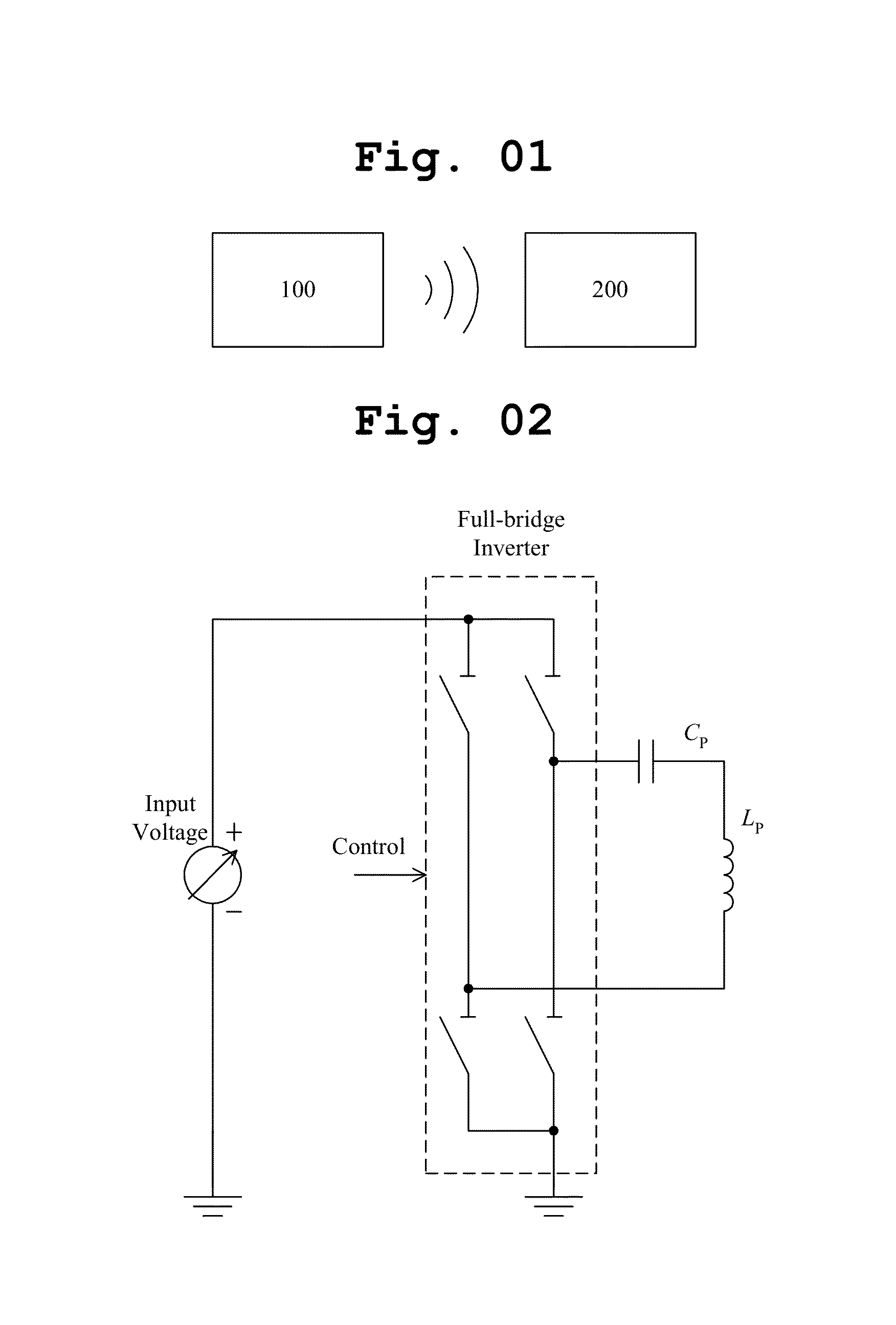
[0032]FIG. 1 conceptually illustrates that power is wirelessly transmitted from a wireless power transmitting apparatus to an electronic apparatus.

[0033]The wireless power transmitting apparatus 100 may be a power transferring apparatus wirelessly transferring power required by a wireless power receiving apparatus or an electronic apparatus 200 or a wireless charging apparatus for charging a battery by wirelessly transferring the power or be implemented by various types of apparatuses transferring the power to the electronic apparatus 200 requiring the power with non-contact.

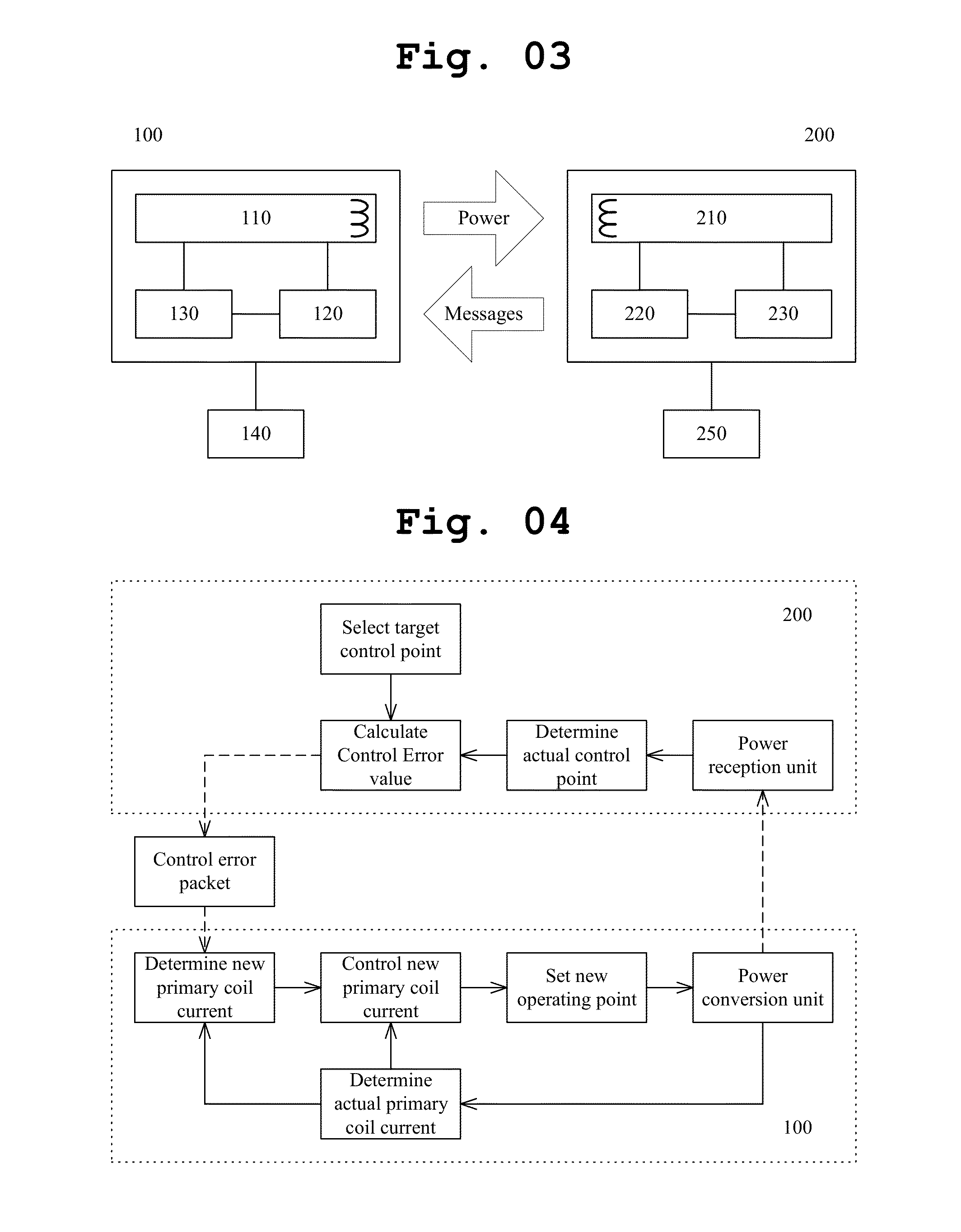
[0034]The electronic apparatus 200 as an apparatus that may operate by wirelessly receiving the power from the wireless power transmitting apparatus 100 may charge the battery by using the wirelessly received power. The electronic a...


PUM


Abstract

The present invention relates to a method and an apparatus for wirelessly transmitting power. A method for wirelessly transmitting power according to an embodiment can measure and store signal strength values corresponding to inductive coupling degrees with a secondary coil of a receiving apparatus sequentially with respect to two or more primary coils included in two or more resonance circuits, select a primary coil related to a largest signal strength value among the signal strength values as an operating coil, adjust a reference value of a power loss value which becomes a basis for entering a mode for detecting power loss based on a difference between a signal strength for a primary coil adjacent to the operating coil and a signal strength value for the operating coil, and transmit power to a wireless power receiving apparatus through the operating coil.

Description

BACKGROUND[0001]1. Field[0002]The present invention relates to an apparatus and a method for transmitting power wirelessly.[0003]2. Related Art[0004]With the development of communication and information processing technology, the use of a smart terminal such as a smart phone, or the like has gradually increased and a charging scheme primarily applied to the smart terminal at present is a scheme in which an adapter connected to a power source is directly connected to the smart terminal to be charged by receiving external power or connected to the smart terminal through a USB terminal of a host to be charged by receiving USB power of the host.[0005]In recent years, in order to reduce inconvenience that the smart terminal should be directly connected to the adapter or the host through a connection line, a wireless charging scheme in which a battery is wirelessly charged by using magnetic coupling without an electric contact has been gradually applied to the smart terminal.[0006]There a...

Claims


Application Information

Patent Timeline
Patent Type & Authority Applications(United States)
IPC IPC(8): H02J5/00
CPCH02J5/005H02J50/12H02J50/70H02J50/402H02J50/80H01F38/14H02J50/40H02J7/00
Inventor HWANG, HOSUNG
Owner HITACHI LG DATA STORAGE KOREA
Why Eureka
Try Eureka