
Electronic component

a technology of electronic components and components, applied in the field of electronic components, can solve the problems of difficult to obtain a high effective magnetic permeability in the electronic component, and achieve the effect of high effective magnetic permeability

Active Publication Date: 2016-04-07
MURATA MFG CO LTD
View PDF2 Cites 14 Cited by
  • Summary
  • Abstract
  • Description
  • Claims
  • Application Information

AI Technical Summary

Benefits of technology

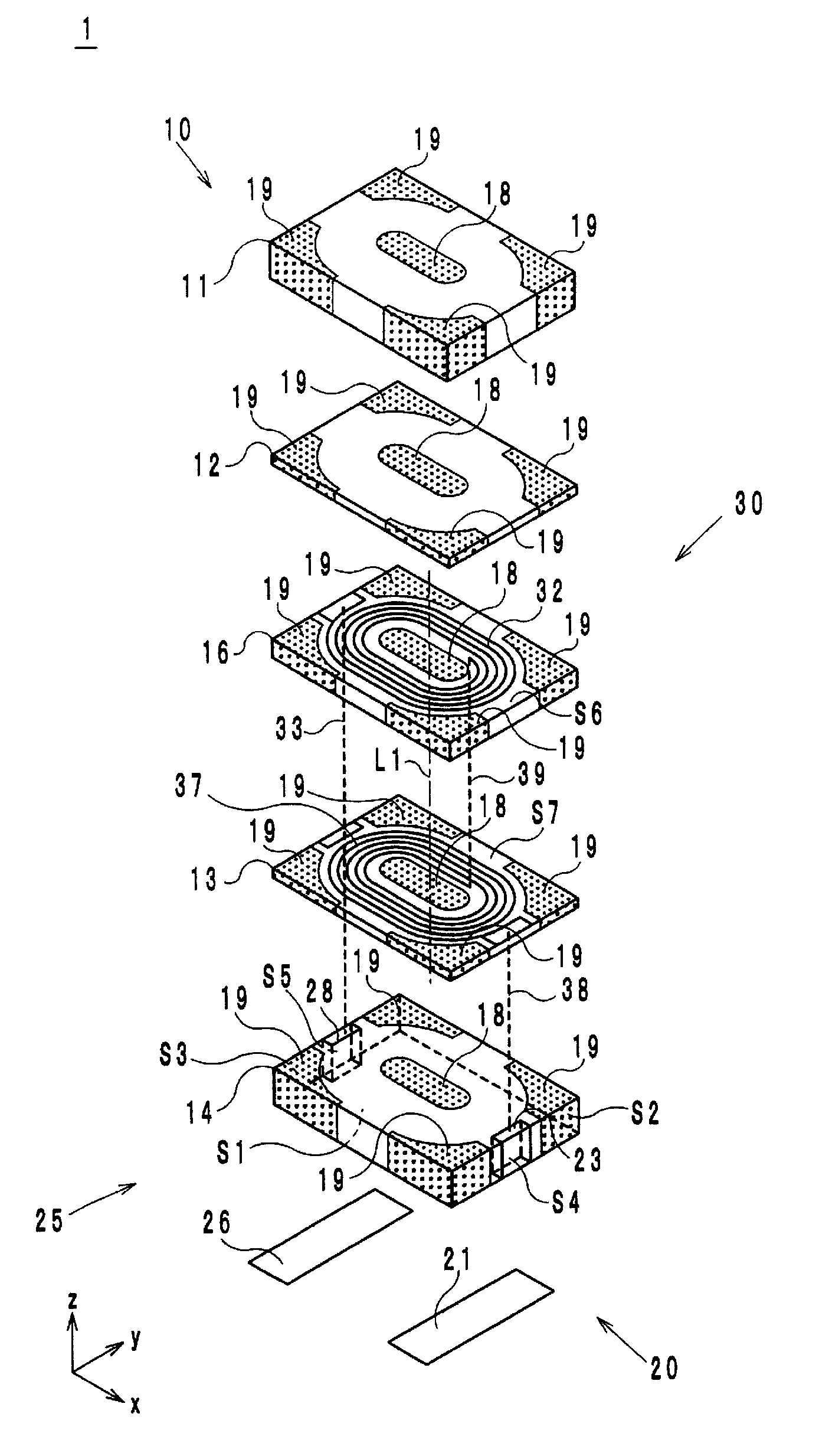
The patent describes an electronic component that utilizes both isotropic and anisotropic magnetic materials with a built-in coil. The invention results in a high effective magnetic permeability, which is useful in improving the performance of the component.

Problems solved by technology

Therefore, it is difficult to obtain a high effective magnetic permeability in the electronic component 510.

Method used


Image

  • Electronic component
  • Electronic component
  • Electronic component

Examples


first modification

[0070]A first modification will be described with reference to FIG. 18. An electronic component 1A of the first modification differs from the electronic component 1 of the embodiment in that the internal magnetic circuit 18 of the electronic component 1A does not penetrate all the way through the insulator layer 13 or the insulator layer 14 as illustrated in FIG. 18. In addition, an end portion of the internal magnetic circuit 18 on the negative side in the z-axis direction, that is, a bottom portion of the internal magnetic circuit 18 has a substantially conical shape.

[0071]In the thus-structured electronic component 1A, the area of contact between the isotropic magnetic material and the anisotropic magnetic material is larger and therefore the strength of the joining between these two materials is higher than in the electronic component 1.

second modification

[0072]A second modification will be described with reference to FIG. 19. An electronic component 1B of the second modification differs from the electronic component 1 of the embodiment in that a portion T1 of the internal magnetic circuit 18 that penetrates through the insulator substrate 16 is formed of the anisotropic magnetic material and a portion T2 of the external magnetic circuit 19 that penetrates through the insulator substrate 16 is formed of the anisotropic magnetic material as illustrated in FIG. 19. In addition, a direction of easy magnetization of the portion T1 of the internal magnetic circuit 18 that penetrates through the insulator substrate 16 and a direction of easy magnetization of the portion T2 of the external magnetic circuit 19 that penetrates through the insulator substrate 16 are parallel to the z-axis direction.

[0073]In the thus-structured electronic component 1B, the magnetic flux generated by the coil 30 advances along the direction of easy magnetization...


PUM

PropertyMeasurementUnit
thicknessaaaaaaaaaa
particle diameteraaaaaaaaaa
anisotropicaaaaaaaaaa

Abstract

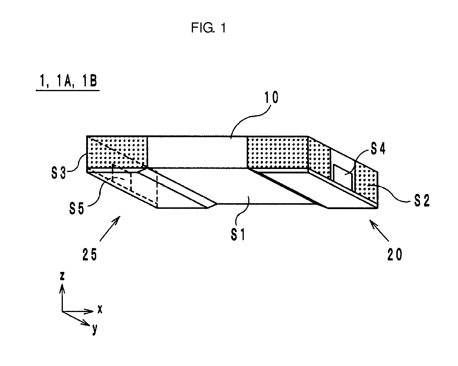
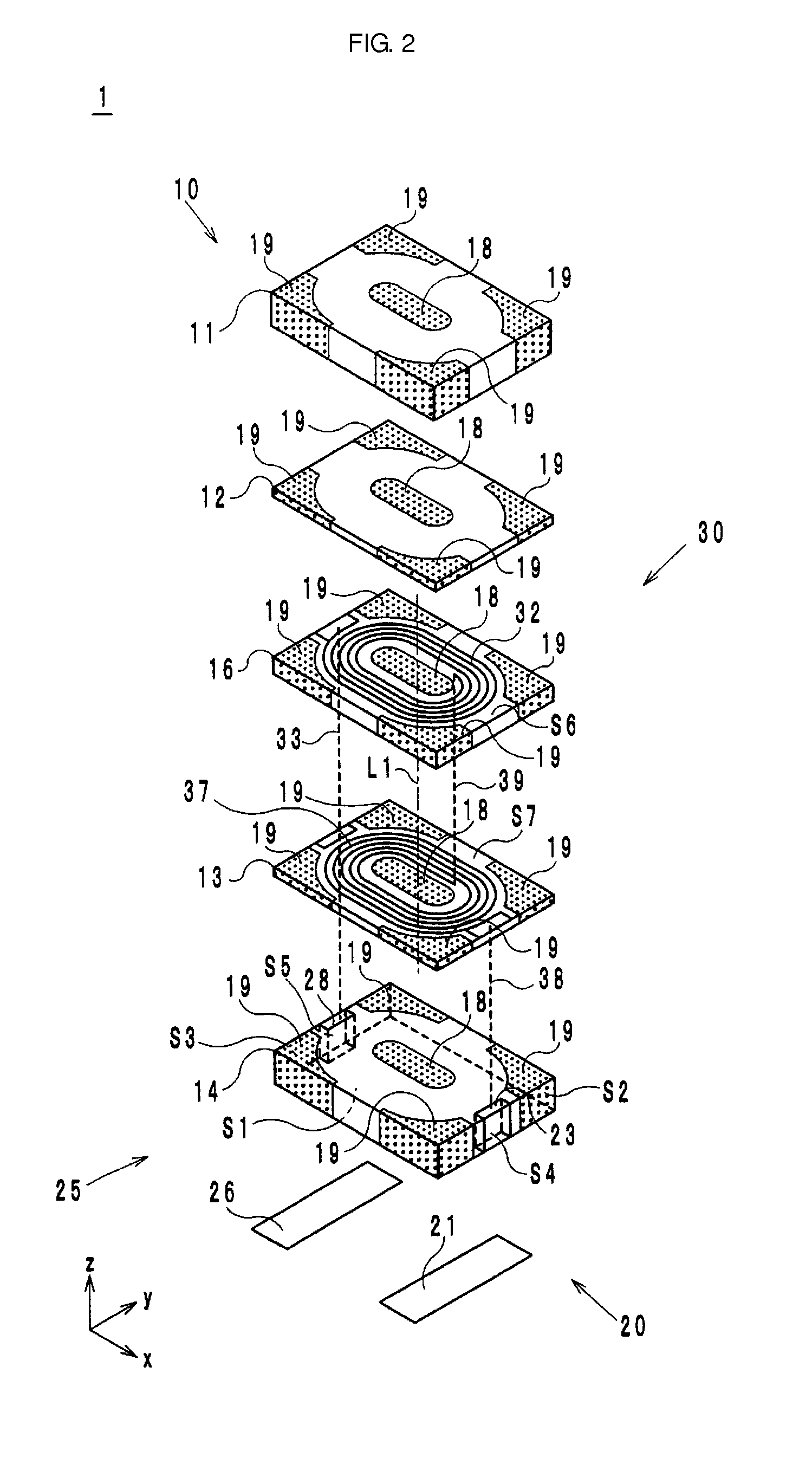
An electronic component includes a body and a coil. The body includes first to fourth insulator layers composed of an anisotropic magnetic material, an internal magnetic circuit composed of an isotropic magnetic material and an external magnetic circuit composed of an isotropic magnetic material. The second and third insulator layers cover an upper surface and a lower surface of the coil from a z-axis direction. The internal magnetic circuit and the external magnetic circuit are adjacent to each other in a direction orthogonal to the z-axis direction. In addition, a direction of easy magnetization of the anisotropic magnetic material used in the first to fourth insulator layers is orthogonal to the z-axis direction.

Description

CROSS REFERENCE TO RELATED APPLICATIONS[0001]This application claims benefit of priority to Japanese Patent Application No. 2014-203140 filed Oct. 1, 2014, the entire content of which is incorporated herein by reference.BACKGROUND[0002]1. Technical Field[0003]The present disclosure relates to an electronic component and in particular relates to an electronic component employing an isotropic magnetic material and an anisotropic magnetic material and having a built-in coil.[0004]2. Description of the Related Art[0005]The coil component described in Japanese Patent No. 5054445 is an example of a known electronic component employing an isotropic magnetic material and an anisotropic magnetic material and having a built-in coil. In an electronic component 510 of this type (electronic component of the related art), sheets 520, which are composed of an anisotropic magnetic material, are stacked on an upper surface and a lower surface of a coil 512, as illustrated in FIG. 21. In addition, a ...

Claims


Application Information

Patent Timeline
Patent Type & Authority Applications(United States)
IPC IPC(8): H01F27/24
CPCH01F27/24H01F17/0006H01F17/04H01F27/292
Inventor YAMAGUCHI, KOICHIKITAJIMA, MASAKIHAMADA, AKINORI
Owner MURATA MFG CO LTD
Learn More