
Pressure Bandage

a technology of pressure bandage and bandage, applied in the field of pressure bandage, can solve the problems of increasing the risk of infection at the site, prolonging the healing time and hospital stay, and a single implant carries multiple risks

Active Publication Date: 2016-04-07
CARDIAC EP EDUCATION & INNOVATION LLC
View PDF6 Cites 9 Cited by
  • Summary
  • Abstract
  • Description
  • Claims
  • Application Information

AI Technical Summary

Benefits of technology

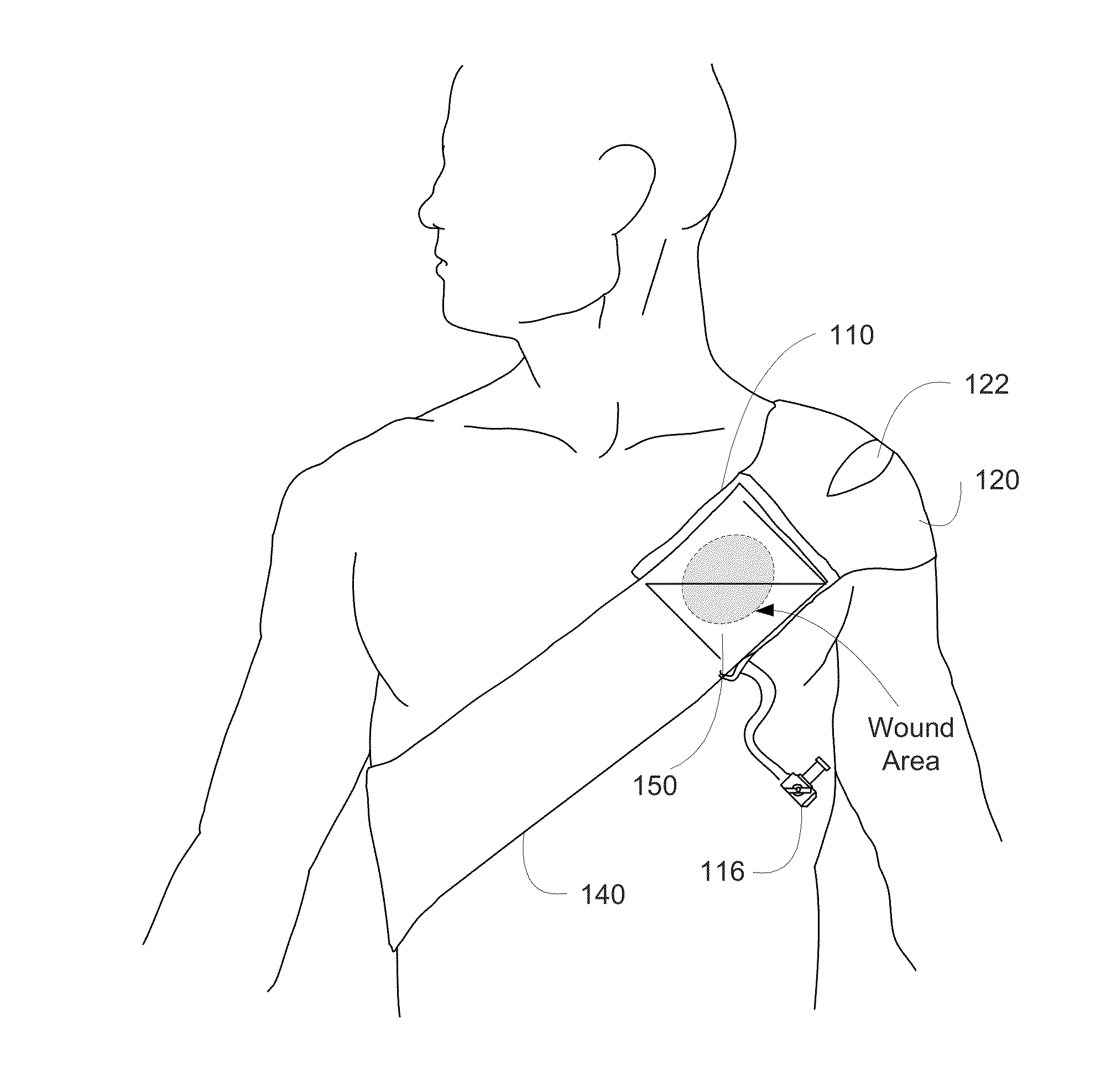
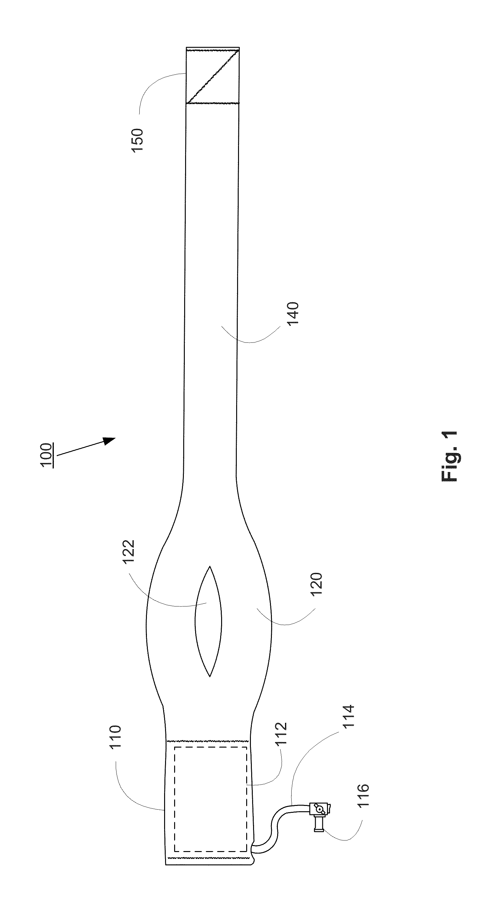
The present invention is a pressure bandage designed to reduce complications after pacemaker and implantable cardiac device (ICD) implants. The bandage is made of an elastic band with a shoulder strap and an inflatable bladder. It can be used to apply pressure to the wound area to decrease hematoma formation and other complications. The bandage is lightweight and comfortable to wear. The technical effect of the invention is to provide a simple and effective solution to reduce post-operative wound complications and improve patient outcomes.

Problems solved by technology

Each implant carries multiple risks, one of the most frequent of these being hematoma formation, which occurs anywhere from 2-5% of cases.
Hematoma (localized bleeding) increases discomfort, dramatically prolongs healing time and hospital stay, raises the risk of infection at the site, and is disappointing to both patient and physician alike.
Moreover, the risk of these bleeds may be increasing as patients are often maintained on anticoagulant and antiplatelet medications through the entire procedural timeframe.
This may be inexpensive but it is awkward and the tape removal painful.
Furthermore, the adhesive tape may cause in allergic reaction in the patient's skin.
The addition of an arm sling offers little benefit, and if kept in place too long, it may cause shoulder joint problems such as adhesive capsulitis that can require weeks of physical therapy.

Method used


Image

  • Pressure Bandage
  • Pressure Bandage
  • Pressure Bandage

Examples


Embodiment Construction

[0014]In order that the invention herein described may be fully understood, the following detailed description is set forth. Various embodiments of the invention are described in detail and may be further illustrated by the provided examples. Additional viable variations of the embodiments can easily be envisioned.

[0015]Unless defined otherwise, all technical and scientific terms used herein have the same meaning as those commonly understood by one of ordinary skill in the art to which this invention belongs.

[0016]As used in the description herein and throughout the claims that follow, the meaning of “a,”“an,” and “the” includes plural reference unless the context clearly dictates otherwise.

[0017]The present invention is drawn to a pressure bandage to focus pressure on fresh pacemaker and defibrillator implant sites to decrease post-operative wound complications. The pressure bandage comprises an elastic band having a shoulder strap component. A pocket is integrated on a portion of ...


PUM


Abstract

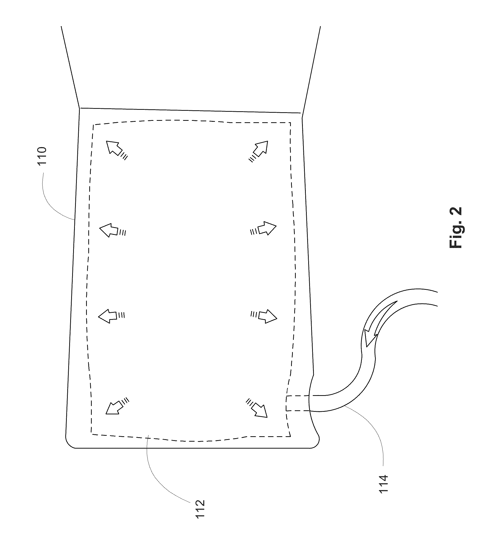
A pressure bandage comprising an elastic band having a first end comprising a pocket member and a second end that is removably attachable to the first end. An inflatable bladder is placed in the pocket member and provides a substantially uniform pressure over a wound area when the band is placed on a patient and the bladder is inflated. The bladder is connected to a tube element which is used to inflate the bladder to the desired pressure. The elastic band may include a shoulder strap and may wrap over a patient's shoulder, across the patient's chest, and under the patient's opposite arm. The bottom side of the elastic band (facing the patient) may be made of a soft, absorptive material, and the bottom side of the pocket member may include an expandable mesh.

Description

FIELD OF THE DISCLOSURE[0001]The present invention relates to a pressure bandage for reducing pacemaker and ICD wound complications.BACKGROUND OF THE INVENTION[0002]Each year over 1 million pacemaker and implantable cardioverter defibrillator (ICD) implants are performed around the world. Each implant carries multiple risks, one of the most frequent of these being hematoma formation, which occurs anywhere from 2-5% of cases. Hematoma (localized bleeding) increases discomfort, dramatically prolongs healing time and hospital stay, raises the risk of infection at the site, and is disappointing to both patient and physician alike.[0003]Moreover, the risk of these bleeds may be increasing as patients are often maintained on anticoagulant and antiplatelet medications through the entire procedural timeframe. Hematomas are now regarded as a measurable complication that can affect a physicians' quality metrics and reimbursement. In fact, Centers for Medicare & Medicaid Services (CMS) has inc...

Claims


Application Information

Patent Timeline
Patent Type & Authority Applications(United States)
IPC IPC(8): A61F13/00
CPCA61F2013/00127A61F13/00068A61F13/14A61F5/30A61F5/34A61F13/05A61F2013/00102A61F2013/00119
Inventor JOYNER, CHARLES A.
Owner CARDIAC EP EDUCATION & INNOVATION LLC
Learn More