Ride-through and recovery method for DC short circuit faults of hybrid mmc-based HVDC system
a hvdc system and hybrid technology, applied in the field of multi-level power electronic converters, can solve the problems of complex timing of restart coordinating actions, high probability of dc faults, and high cost, and achieve fast fault response and recovery, improve transient stability of connected ac system and connected dc system, and improve the effect of performan
- Summary
- Abstract
- Description
- Claims
- Application Information
AI Technical Summary
Benefits of technology
Problems solved by technology
Method used
Image
Examples
example 1
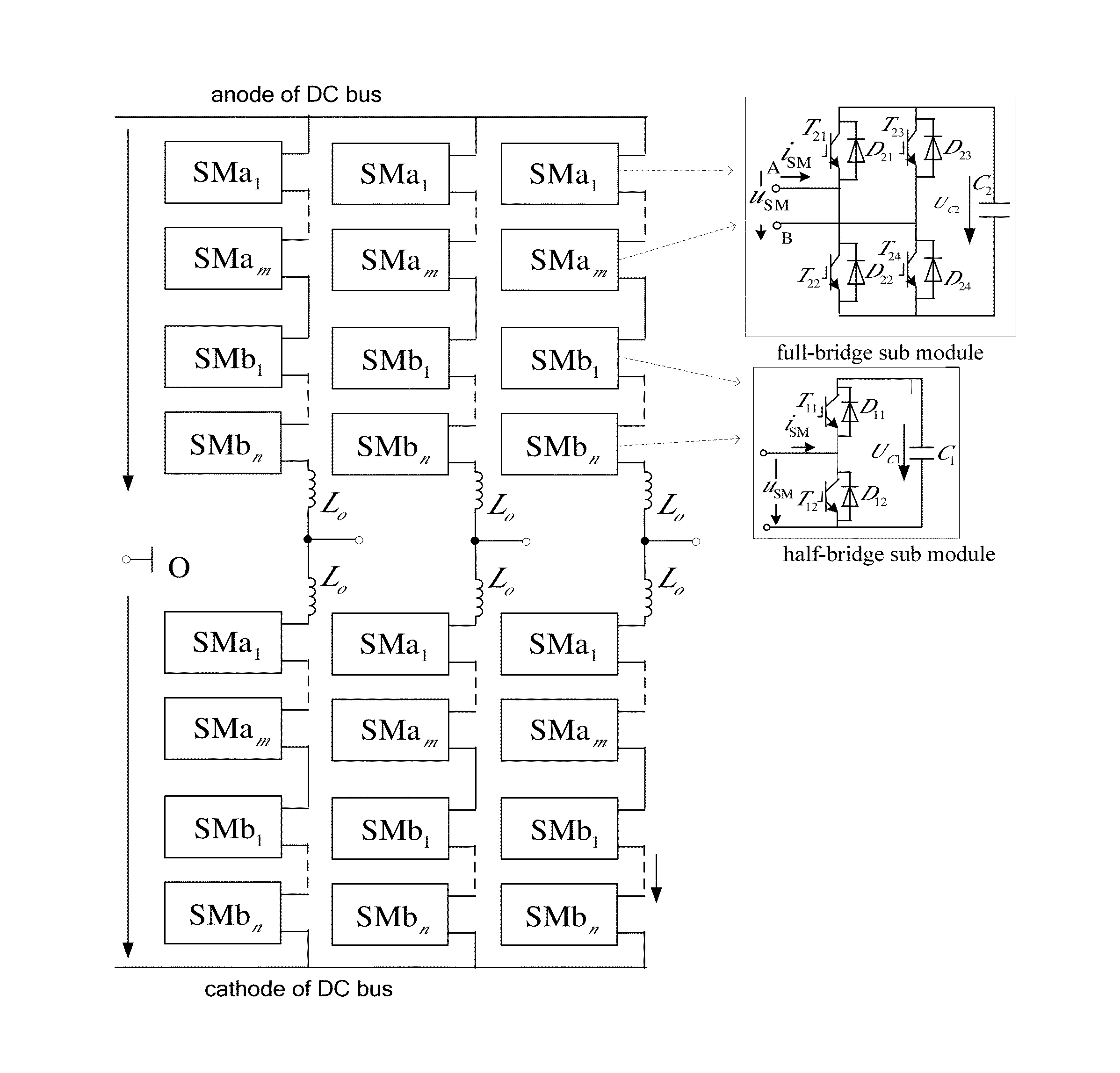
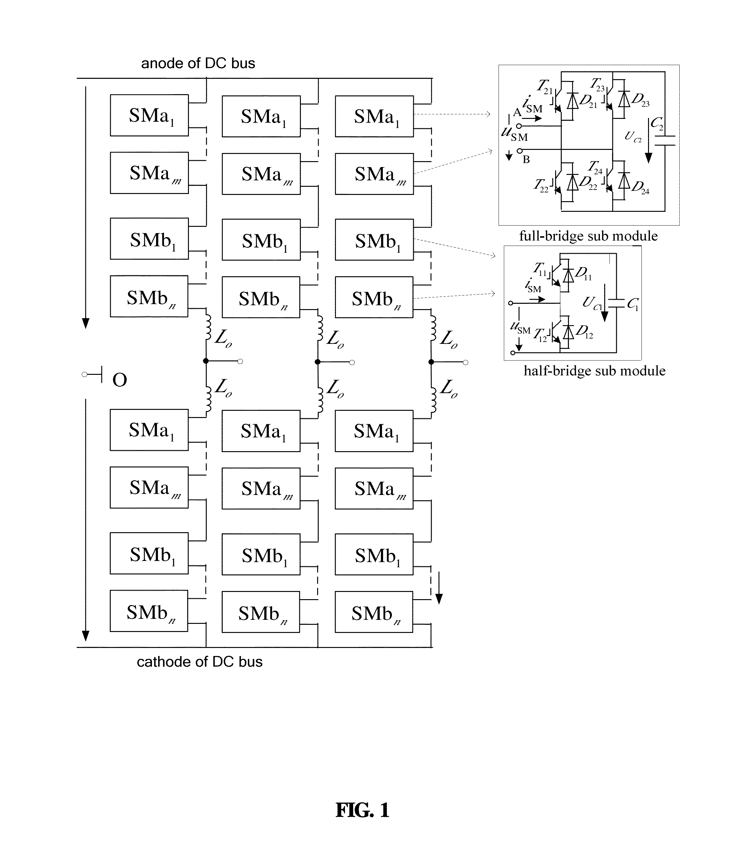
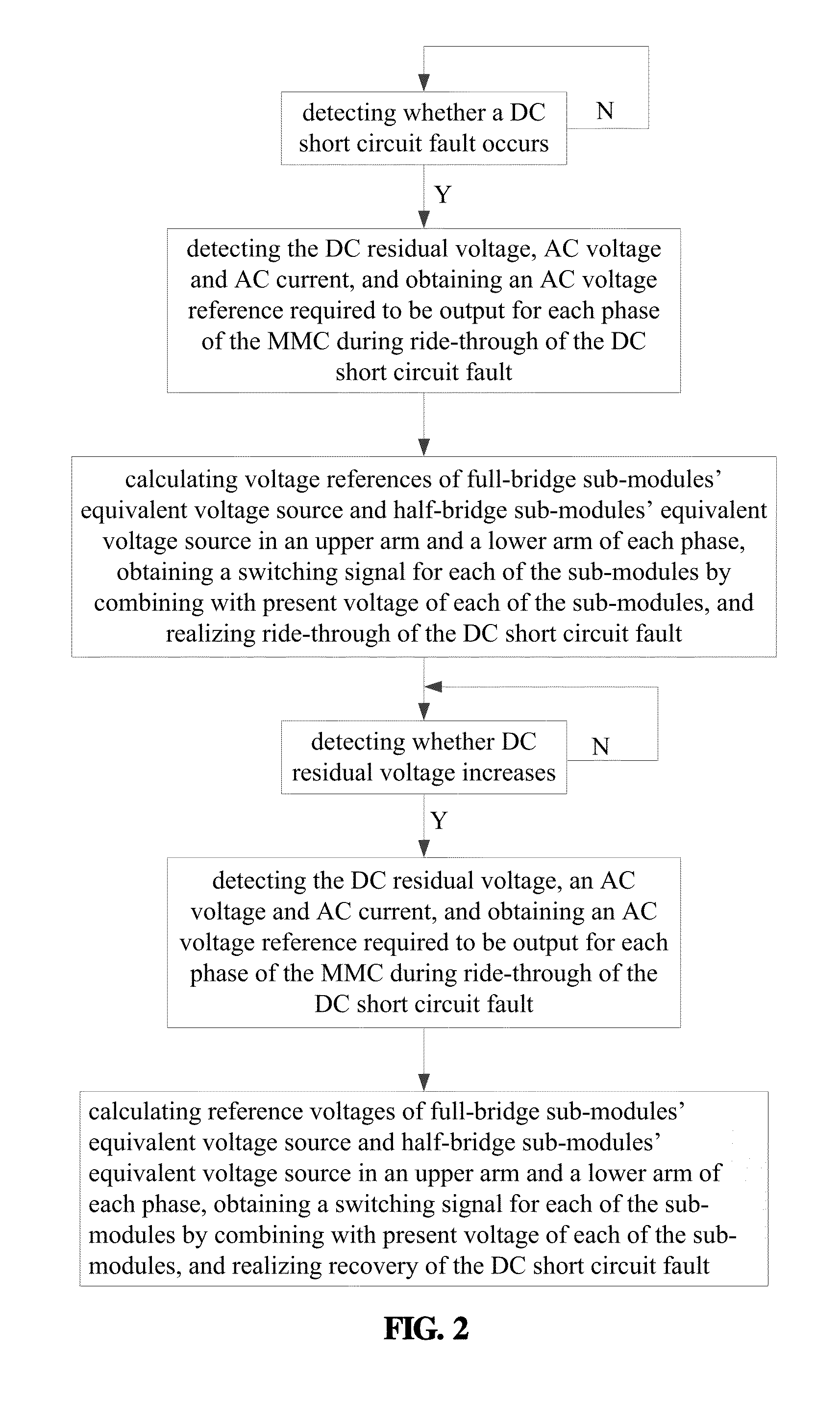
[0078]A DC short circuit fault is detected and a DC voltage becomes 0 kV. An active reference power required to be transmitted by a hybrid MMC is set to 0 mW, and a reactive reference power required to be transmitted to an AC system is set to 1 mVAR according to requirements for stability of the connected AC system and DC lines. The AC voltage reference eiv_ref required to be output for each phase of the MMC during ride-through of the DC short circuit fault is obtained. uif_p, uih_p, uif_n, and uih_n, are calculated and expressed by the following equations:
uif_p=−eiv_ref(1−½m)+Udc¼m,
uih_p=−eiv_ref½m+Udc¼m,
uif_n=eiv_ref(1−½m)+Udc¼m, and
uih_n=eiv_ref½m+Udc¼m;
[0079]Switching signal for each of the sub-modules is obtained by combining with a present voltage of each of the sub-modules. The DC voltage is detected to be restored to a rated value. The active power reference and the reactive power reference for the hybrid MMC are set to values in normal operation, that is, the transmitted...
example 2
[0082]A DC short circuit fault is detected and a DC voltage becomes 0 kV. An active reference power required to be transmitted by a hybrid MMC is set to 0 mW, and a reactive reference power required to be transmitted to an AC system is set to 1 mVAR according to requirements for stability of the connected AC system and DC lines. The AC voltage reference eiv_ref required to be output for each phase of the MMC during ride-through of the DC short circuit fault is obtained. uif_p, uih_p, iif_n, and uih_n are calculated and expressed by the following equations:
uif_p=−½eiv_ref−¼Udc+½mUdc,
uih_p=−½eiv_ref+¼Udc,
uif_n=½eiv_ref−¼Udc+½mUdc, and
uih_n=½eiv_ref+¼Udc;
[0083]Switching signal for each of the sub-modules is obtained by combining with a present voltage of each of the sub-modules. The DC voltage is detected to be restored to a rated value. The active power reference and the reactive power reference for the hybrid MMC are set to values in normal operation, in which the transmitted active ...
example 3
[0086]A DC short circuit fault is detected and a DC voltage becomes 0 kV. An active reference power required to be transmitted by a hybrid MMC is set to 0 mW, and a reactive reference power required to be transmitted to an AC system is set to 1 mVAR according to requirements for stability of the connected AC system and DC lines. The AC voltage reference eiv_ref required to be output for each phase of the MMC during ride-through of the DC short circuit fault is obtained. uif_p, uih_p, uif_n, and uih_n are calculated and expressed by the following equations:
uif_p=-eiv_ref(1-x-12m+xm)+Udc(14m+xm2-x2),uih_p=-eiv_ref(x+12m-xm)+Udc(14m-xm2+x2),uif_n=eiv_ref(1-x-12m+xm)+Udc(14m+xm2-x2),anduih_n=eiv_ref(x+12m-xm)+Udc(14m-xm2+x2);
[0087]where x=0.2. Switching signal for each of the sub-modules is obtained by combining with a present voltage of each of the sub-modules. The DC voltage is detected to be restored to a rated value. The active power reference and the reactive power reference for th...
PUM
 Abstract
Description
Claims
Application Information
 - R&D
- Intellectual Property
- Life Sciences
- Materials
- Tech Scout
- Unparalleled Data Quality
- Higher Quality Content
- 60% Fewer Hallucinations
Browse by: Latest US Patents, China's latest patents, Technical Efficacy Thesaurus, Application Domain, Technology Topic, Popular Technical Reports.
© 2025 PatSnap. All rights reserved.Legal|Privacy policy|Modern Slavery Act Transparency Statement|Sitemap|About US| Contact US: help@patsnap.com


