Zone Plate and Method for Fabricating Same Using Conformal Coating

Inactive Publication Date: 2016-03-24
CARL ZEISS X RAY MICROSCOPY
View PDF26 Cites 18 Cited by
  • Summary
  • Abstract
  • Description
  • Claims
  • Application Information

AI Technical Summary

Benefits of technology

The present invention provides a system and method for improving the efficiency of ALD zone plates or ozone plates fabricated using a similar conformal coating process. The invention can provide efficiency improvements for zones across all sections of the zone plate, especially for the zones of innermost sections. The invention achieves the efficiency improvement by designing a template that allows for thicker zone widths and increasing the spatial frequency of the annular rings of the template. The result is wider zones that increase the duty cycle of the zones, improving their diffraction efficiency as compared to conventional ALD zone plates.

Problems solved by technology

As a result, though the ALD process provides many fabrication advantages over traditional methods, by design, conventional ALD zone plates suffer from decreased efficiency by as much as 30% as compared to an ideal zone plate.

Method used


Image

  • Zone Plate and Method for Fabricating Same Using Conformal Coating
  • Zone Plate and Method for Fabricating Same Using Conformal Coating
  • Zone Plate and Method for Fabricating Same Using Conformal Coating

Examples


first embodiment

[0060]FIGS. 6A-6C compare cross-sectional views for the same sections 102 of three different zone plates 100. The figures compare cross-sections of zones of an ideal binary zone plate in FIG. 6A, cross-sections including zones and a template 160 of a conventional ALD zone plate in FIG. 6B, and cross-sections including zones and a template 160 of an inventive ALD zone plate constructed according to the present invention in FIG. 6C.

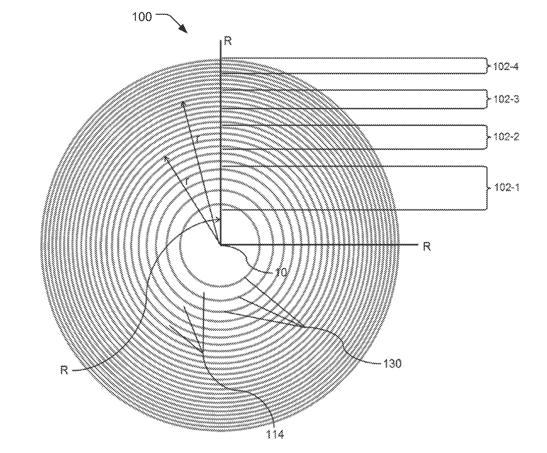
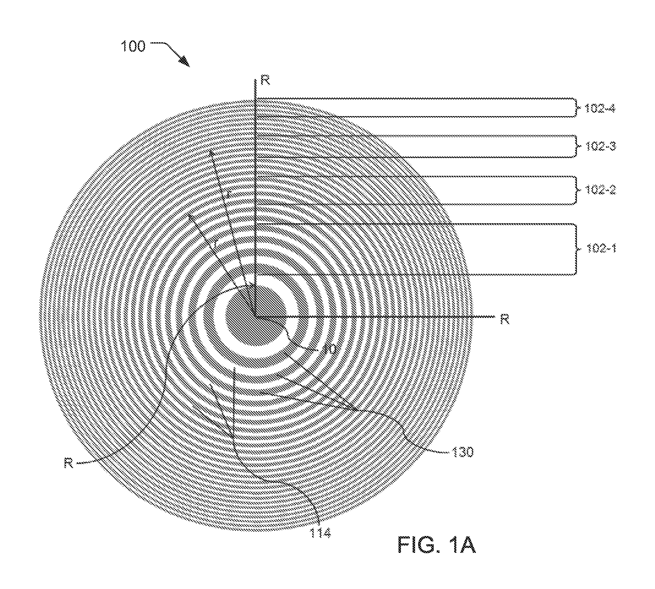
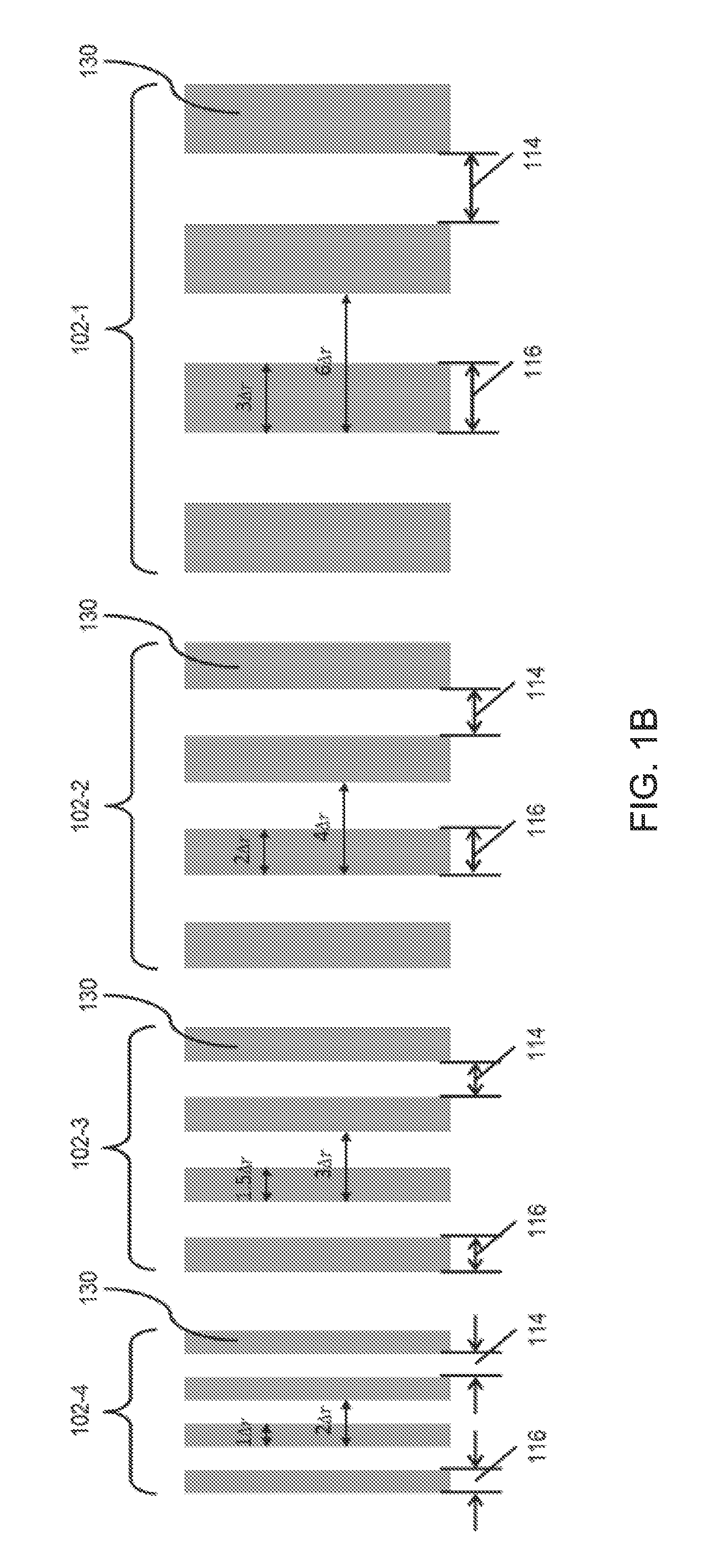
[0061]Of the sections, there is an outermost section 102-4, a third inner section 102-3, a second inner section 102-2, and a first inner section 102-1. For each section 102, the ideal zone width 116 of the zones 130 is a multiple of Δr, the zone width of the outermost zones. The ideal zone width at local radius r is also known as Wr.

[0062]The first inner section 102-1 includes zones having a local radius r on the order of ⅓ times the radius R of the zone plate, measured from the center 10 of the zone plate 100. The zone widths 116 of the zones 130 in the fi...

second embodiment

[0082]The second embodiment provides wider zones as compared to the conventional ALD zone plate in FIG. 7B, with up to twice the ALD layer coating depth or thickness for the inner zones which are zones associated with sections 102-1, 102-2, and 102-3. For the outer zones, in section 102-4, the spacing of annular rings 140 is arranged so that the width of the annular channels 150 exceeds the ALD layer thickness. The consequence is that the annular channels 150 are not filled but the sidewalls 140 of the annular rings 160 are coated. This provides the frequency doubling effect found in conventional ALD zone plates.

[0083]FIGS. 8A-8D show cross-sectional views according to embodiments of the inventive zone plate at different times or phases when depositing the conformal coating layer to form wider zones 130. FIG. 8A provides a view of the deposition process at the point where the sidewalls 140 are initially coated, as during the formation of zones 130 for conventional ALD zone plates as...


PUM

PropertyMeasurementUnit
Thicknessaaaaaaaaaa
Ratioaaaaaaaaaa
Efficiencyaaaaaaaaaa

Abstract

A system and method for improving efficiency of zone plates fabricated by conformal layer coatings is disclosed. In embodiments, the inventive conformal layer coating zone plates provide increased zone widths from one times a deposited conformal layer coating thickness up to and including two times the conformal layer coating thickness. By designing a template that increases a mark-to-space ratio of the annular rings of the template, coating sidewalls of the annular rings with an conformal layer coating to form the zones, and then substantially filling annular channels defined by the annular rings with the conformal layer coating to form wider zones, significant efficiency increases can be achieved over conventional conformal layer coating zone plates, especially for innermost zones.

Description

RELATED APPLICATIONS[0001]This application claims the benefit under 35 USC 119(e) of U.S. Provisional Application No. 62 / 054,632, filed on Sep. 24, 2014, which is incorporated herein by reference in its entirety.BACKGROUND OF THE INVENTION[0002]Lens-based, high-resolution x-ray microscopy largely resulted from research work at synchrotron radiation facilities in Germany and United States starting in the 1980's. While projection-type x-ray imaging systems with up to micrometer resolution have been widely used since the 1930s, ones using x-ray lens with sub-100 nanometer (nm) resolution began to enter the market only this century. These high-resolution microscopes are configured similarly to visible-light microscopes with an optical train typically including an x-ray source, condenser lens, objective lens, and detector.[0003]Because x rays do not refract significantly in most materials, nearly all such x-ray microscopes use diffractive objective lenses, called Fresnel zone plates. A z...

Claims


Application Information

Patent Timeline
IPC IPC(8): G21K1/06C23C16/455
CPCC23C16/45555G21K1/06G21K1/062C23C16/045
Inventor LEUNG, RAYMONDFESER, MICHAEL
Owner CARL ZEISS X RAY MICROSCOPY
Why Eureka
Try Eureka