
Stiffening element for a motor vehicle frame

a technology for a motor vehicle frame and a stiffening element, which is applied in the direction of roofs, transportation and packaging, vehicle arrangements, etc., can solve the problems that the flat stiffening element cannot absorb such lateral forces, and achieves good distribution of forces, ensure stability, and minimize surface tension

Active Publication Date: 2016-03-24
DR ING H C F PORSCHE AG
View PDF3 Cites 2 Cited by
  • Summary
  • Abstract
  • Description
  • Claims
  • Application Information

AI Technical Summary

Benefits of technology

The invention is a stiffening element that is used in motor vehicles to provide better lateral rigidity support and to protect the steering mechanism from damage. The stiffening element has a unique design that allows it to absorb asymmetrical forces and can be easily installed in a cost-effective manner. It can be made from plastic or metal and can be trimmed to fit different vehicle designs. The stiffening element can also be used as heat protection for the steering mechanism and can be produced using fiber-reinforced plastic or metal. Overall, the stiffening element improves the stability and performance of the vehicle.

Problems solved by technology

Conventional, flat stiffening elements fail to absorb such lateral forces.

Method used


Image

  • Stiffening element for a motor vehicle frame
  • Stiffening element for a motor vehicle frame

Examples


Embodiment Construction

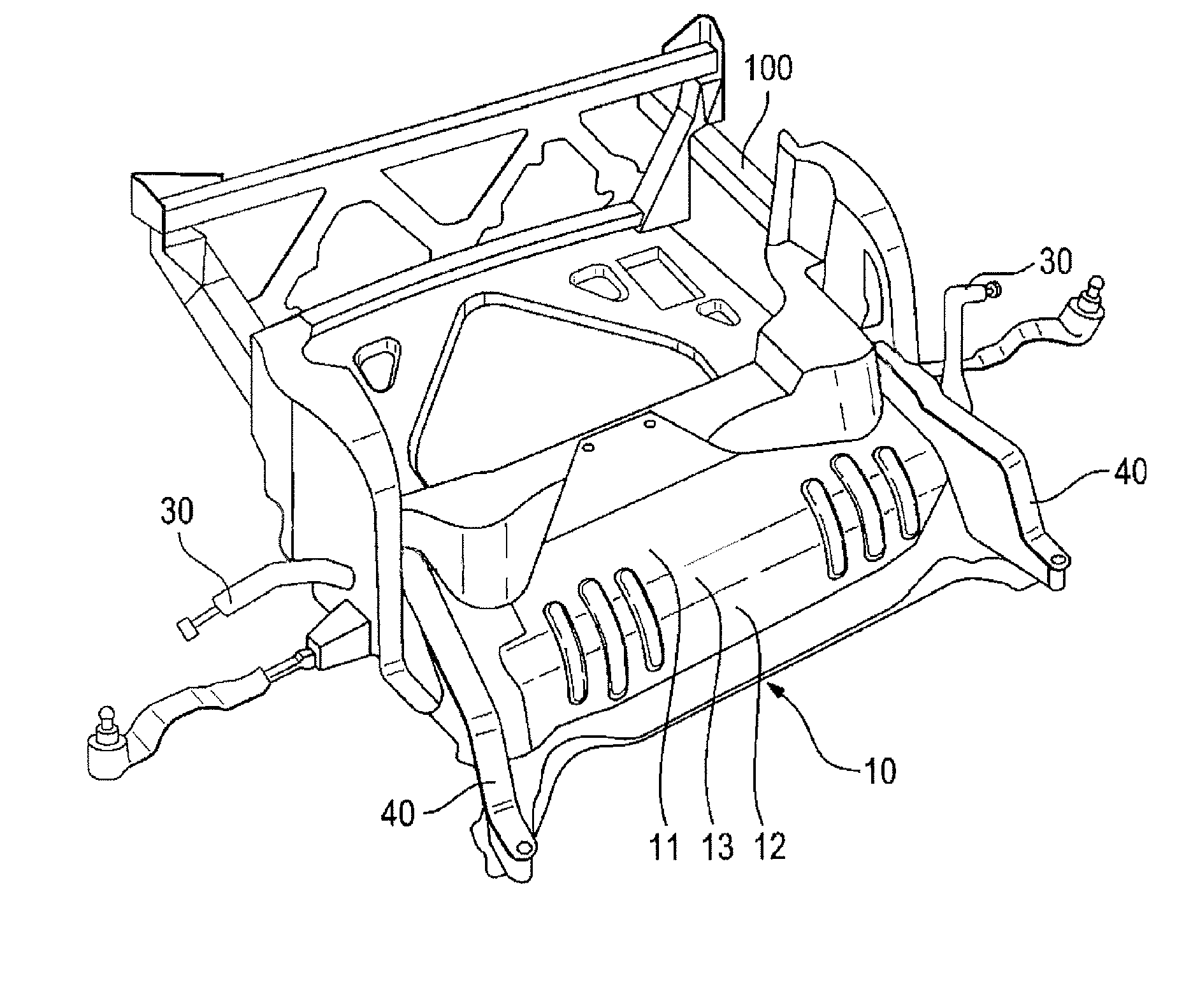
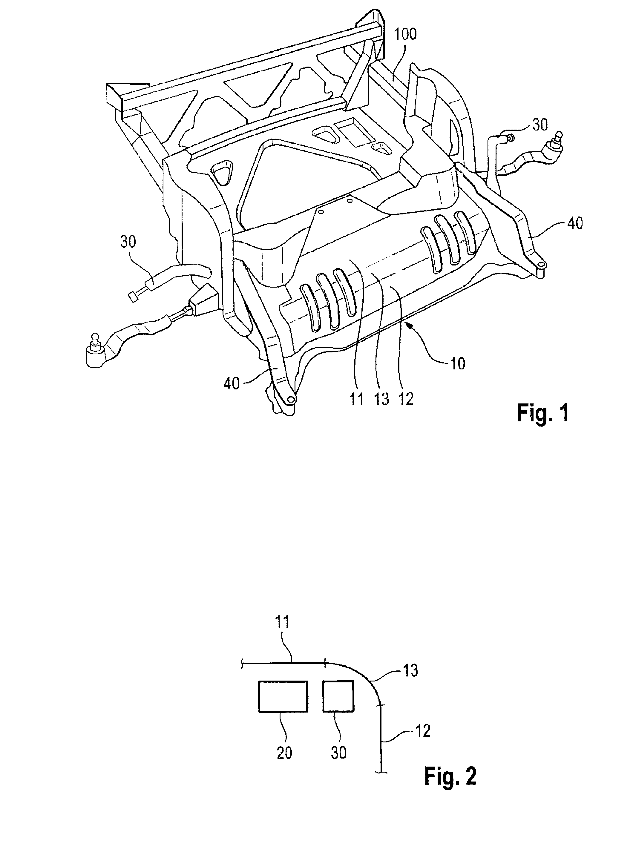
[0022]FIG. 1 illustrates how a stiffening element 10 can be arranged on a subframe 100, and FIG. 2 illustrates how the stiffening element 10 according to aspects of the invention is designed in cross section.

[0023]According to FIGS. 1 and 2, the stiffening element 10 has a substantially horizontal section 11 in order to impart rigidity to the subframe 100 in the horizontal plane, and a substantially vertical section 12 in order to impart rigidity to the subframe 100 in the vertical plane. The stiffening element 10 here is arranged on the subframe 100 above a steering mechanism 20. The steering mechanism 20 is shown schematically, and it may comprise track rods, steering gears, and / or tie rods. In addition, the stiffening element 10 has a curved section 13 between the horizontal section 11 and the vertical section 12 in order to form a flowing transition between the horizontal section 11 and the vertical section 12 and to provide stability between two planes 11, 12 of the stiffening ...


PUM


Abstract

A stiffening element for a subframe of a motor vehicle, including a substantially horizontal section in order to confer rigidity to the subframe in the horizontal plane, and a substantially vertical section in order to confer rigidity to the subframe in the vertical plane, wherein the stiffening element is designed in such a manner that the stiffening element is arrangeable on the subframe above a steering mechanism.

Description

CROSS-REFERENCE TO RELATED APPLICATION[0001]This application claims priority to German Patent Application No. 10 2014 113 565.2, filed Sep. 19, 2014, which is incorporated by reference herein in its entirety.FIELD OF THE INVENTION[0002]The present invention relates to a stiffening element for a subframe of a motor vehicle and to a subframe for a motor vehicle.BACKGROUND OF THE INVENTION[0003]It is known to use stiffening elements for motor vehicle subframes, which are likewise referred to as shear areas. In recent years, subframes have been designed to be increasingly lighter. The stiffening elements serve here to impart the required rigidity to the subframes. Conventional subframes are designed as sheetlike areas which are arranged below the steering mechanism.[0004]A first disadvantage of the known stiffening elements is that, in the case of lower motor vehicles, there is little space available below the steering mechanism for attaching the stiffening elements, in order to attach ...

Claims


Application Information

Patent Timeline
IPC IPC(8): B62D21/00B62D29/00B62D29/04
CPCB62D21/00B62D29/008B62D29/041B62D21/11
Inventor MUNZERT, ANDREAS
Owner DR ING H C F PORSCHE AG
Learn More