
Foam dispensing device utilizing spongy insert

Inactive Publication Date: 2016-03-24
GRANT CALVIN
View PDF0 Cites 0 Cited by
  • Summary
  • Abstract
  • Description
  • Claims
  • Application Information

AI Technical Summary

Benefits of technology

The invention is a device that can produce foam from a liquid solution by using a spongy material with controlled pore size. The device can mix two separately stored solutions as they are converted to foam, which is useful in ophthalmic applications. The spongy material prevents liquid from leaking out of the orifice when the container is inverted. The device allows for consistent and controlled delivery of foam, which is cost-effective and easy to use.

Problems solved by technology

Such designs require a high number of components which results in more complicated production and potentially higher manufacturing costs.
Such designs make creating and dispensing only the intended amount of foam difficult.
Thus, if the device is stored, some of the liquid is unavoidably stored as foam.
On top of the problems listed above, the shredded plastic cannot hold the sponge in one position.
Other sponge-employing devices require a large number of parts.

Method used


Image

  • Foam dispensing device utilizing spongy insert
  • Foam dispensing device utilizing spongy insert
  • Foam dispensing device utilizing spongy insert

Examples


Embodiment Construction

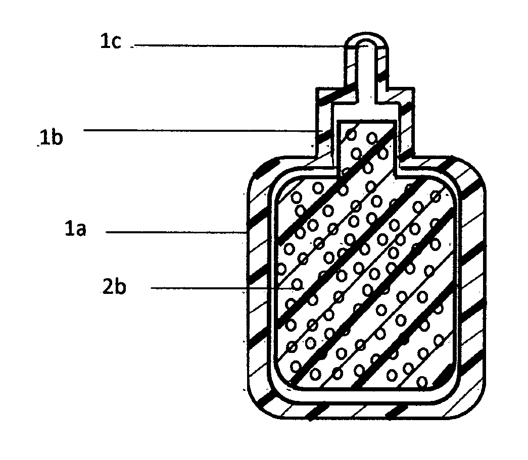
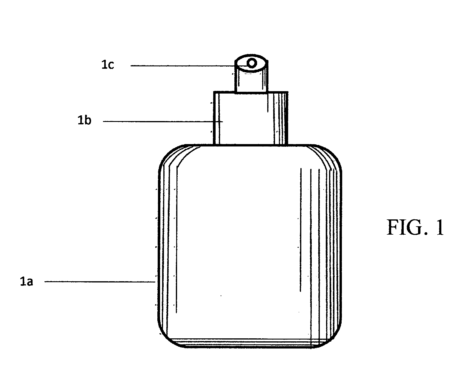
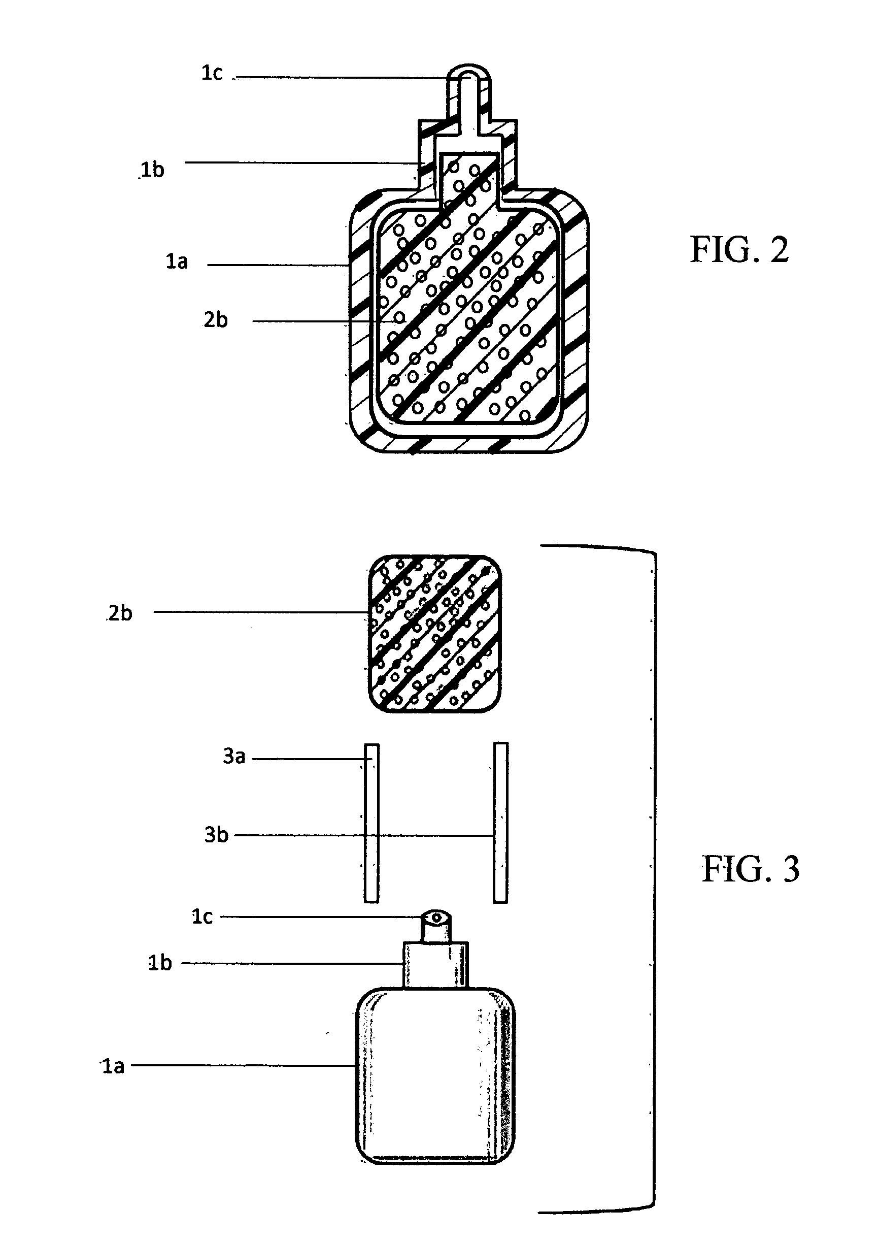
[0024]Referring to FIGS. 1-5, a compressible container 1 has a bottle shaped body 1a, a dispensing section 1b, and a dispensing orifice 1c. The dispensing section 1b protrudes from one end of the body 1a and has a smaller cross sectional area than the body 1a. The orifice 1c is a small hole located on the dispensing section 1b. The compressible container 1 also contains a spongy material 2, which is pictured in FIGS. 2-5.

[0025]In use, the compressible body of the container 1a will be filled with a foamable liquid 4, which is pictured in FIG. 2. The container will be compressed, which will push the foamable liquid 4 through the spongy material 2 and out of the dispensing orifice 1c.

[0026]The spongy material can range from having a small size 2a that occupies only the inside space of the dispensing section, as is pictured in FIGS. 4 and 5, to a larger size 2b that occupies the entire inside space of the bottle, as is pictured in FIGS. 2 and 3. The spongy material 2 is either fitted t...


PUM


Abstract

A foam dispensing device is comprised of a collapsible container and a spongy foam-producing insert. The container consists of a holding section, a dispensing section, and a dispensing orifice. It is filled with a foamable liquid, and, when it is compressed, the foamable liquid is pushed through the foam producing means and exits the orifice as foam. Also claimed is an embodiment of the invention wherein a second solution is stored in the spongy material and dissolved as the foamable liquid is expelled from the container. This device allows for a more simplistic and inexpensive system to deliver foam stored as a foamable liquid. The design also lends itself to be used for various medical applications, especially in ophthalmology.

Description

CROSS REFERENCE TO RELATED APPLICATIONS[0001]Not applicable.STATEMENT REGARDING FEDERALLY SPONSORED RESEARCH AND DEVELOPMENT[0002]Not applicable.REFERENCE TO AN APPENDIX[0003]Not applicable.BACKGROUND OF THE INVENTION[0004]This invention relates to a foam dispenser, for use particularly, but not exclusively, to generate a foamed ophthalmic solution from a foamable liquid solution and air.[0005]A foam can be defined as a relatively large amount of a gas phase dispersed throughout a thin film of liquid. Foam dispensing devices consist of a means to agitate a foamable liquid and gas to create this dispersion, and a means to dispense the foam. Numerous foam dispensing devices have been published in patents and are available commercially.[0006]The present invention is concerned with foam dispensing devices that utilize a deformable mixing reservoir, rather than those which supply a channel of pressurized air to a foamable liquid. This former type of device typically consists of a foam pr...

Claims


Application Information

Patent Timeline
IPC IPC(8): B05B7/00B05B11/04
CPCB05B11/047B05B7/0018B05B11/04
Inventor GRANT, CALVIN
Owner GRANT CALVIN
Learn More