Electronic apparatus
- Summary
- Abstract
- Description
- Claims
- Application Information
AI Technical Summary
Benefits of technology
Problems solved by technology
Method used
Image

Examples
first embodiment
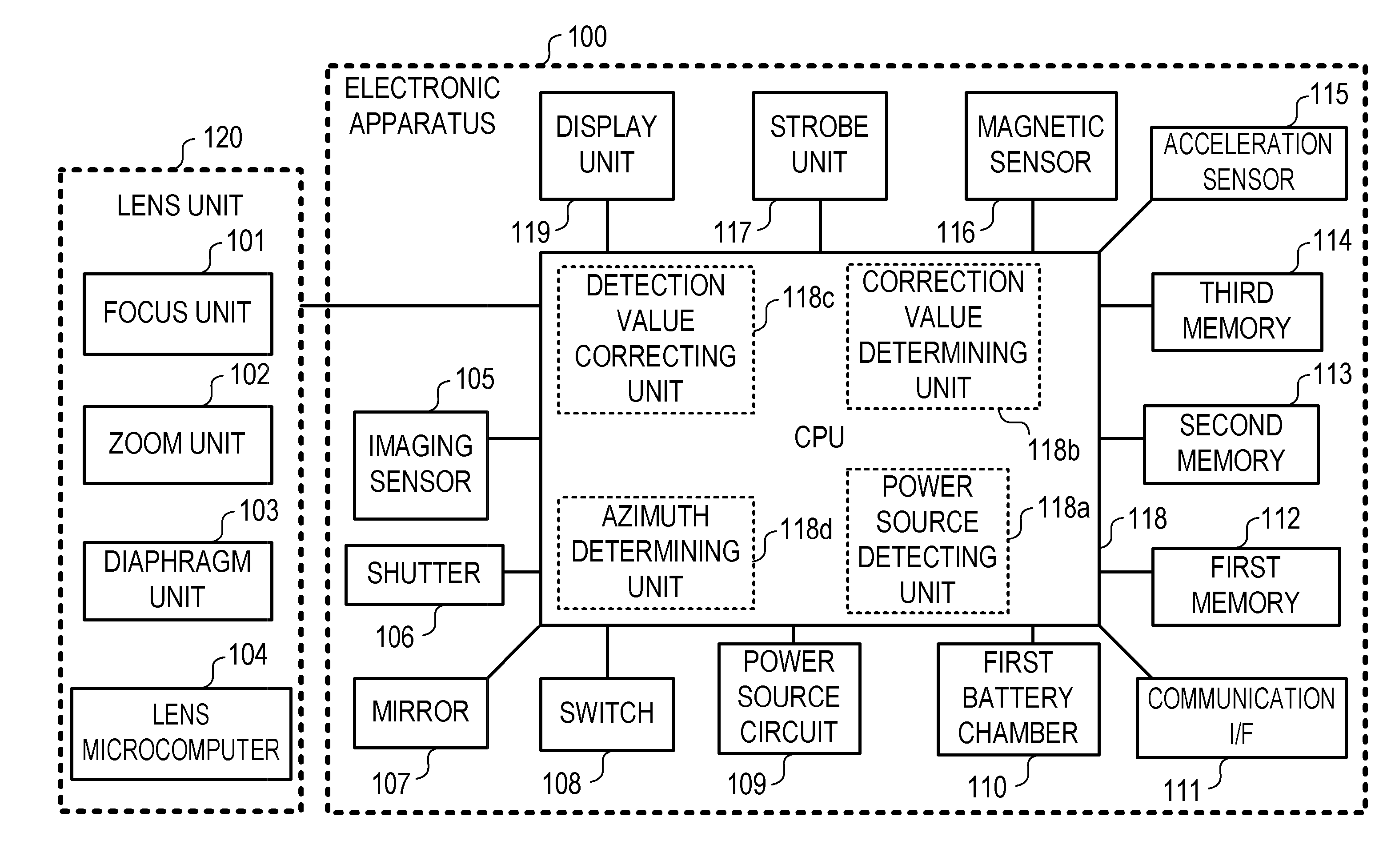
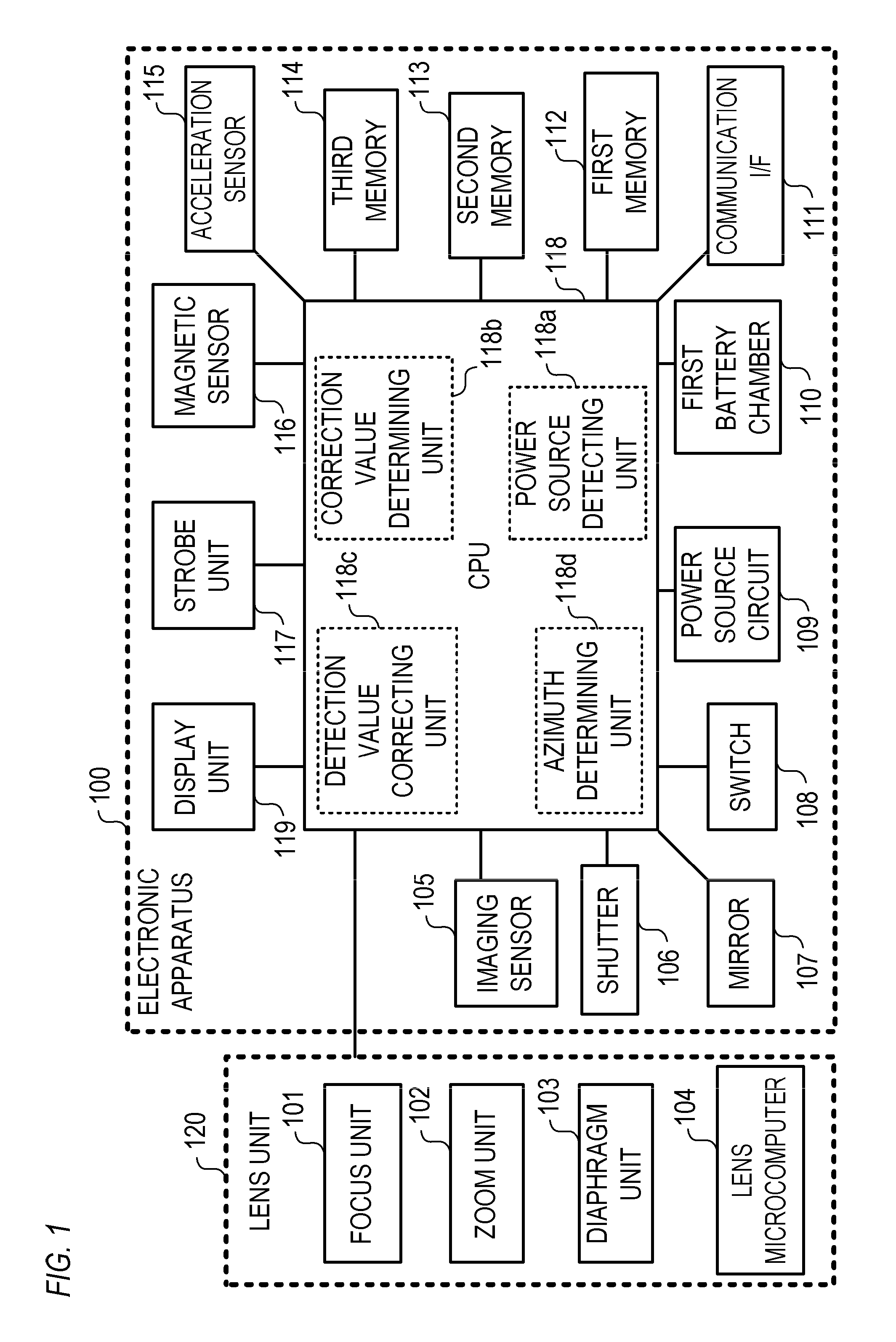
[0032]An electronic apparatus 100 and a control method for the electronic apparatus 100 according to a first embodiment are explained below.
[0033]The electronic apparatus 100 is an electronic apparatus operating as an azimuth detecting apparatus (an electronic compass, etc.) capable of detecting an azimuth in which a predetermined surface (e.g., an imaging surface) of the electronic apparatus 100 is directed. Note that, in the first to third embodiments, an example is explained in which the electronic apparatus 100 is an electronic apparatus operating as an imaging apparatus. However, the electronic apparatus 100 is not limited to the electronic apparatus operating as the imaging apparatus. For example, the electronic apparatus 100 may be an electronic apparatus operating as a digital camera such as a digital single-lens reflex camera. For example, the electronic apparatus 100 may be an electronic apparatus operating as a digital video camera. For example, the electronic apparatus 1...
second embodiment
[0113]The electronic apparatus 100 and a control method for the electronic apparatus 100 according to a second embodiment are explained below.
[0114]In the first embodiment, the example is explained in which the magnetic detection value of the magnetic sensor 116 is corrected on the basis of the type of the power source connected to the first battery chamber 110 and the selected operation mode.
[0115]However, by a change in a state of the power source connected to the first battery chamber 110, the shift amount of the magnetic field detected by the magnetic sensor 116 and a degree of the soft iron effect sometimes change. In a case where the power source connected to the first battery chamber 110 is a battery, the state of the power source include a residual capacity of the battery, a voltage of the battery, a deterioration degree of the battery, and the like.
[0116]Specifically, by consuming electric power retained in the battery, a chemical change occurs on the inside of the battery ...
third embodiment
[0134]The electronic apparatus 100 and a control method for the electronic apparatus 100 according to a third embodiment are explained below.
[0135]In the first and second embodiments, the example is explained in which the type of the power source connected to the first battery chamber 110 is detected.
[0136]In the third embodiment, an example is explained in which a special process is performed in a case where power source information corresponding to a type of a power source connected to the first battery chamber 110 is not acquired from the second memory 113 (or the first memory 112).
[0137]FIG. 10 is a flowchart for illustrating an example of the operation of the electronic apparatus 100 according to the third embodiment.
[0138]First, in S401, the CPU 118 determines whether a state of the power switch is switched to an ON state. By switching the state of the power switch to the ON state, the electronic apparatus 100 starts and the CPU 118 proceeds from S401 to S402.
[0139]In S402, th...
PUM
 Abstract
Description
Claims
Application Information
 - R&D
- Intellectual Property
- Life Sciences
- Materials
- Tech Scout
- Unparalleled Data Quality
- Higher Quality Content
- 60% Fewer Hallucinations
Browse by: Latest US Patents, China's latest patents, Technical Efficacy Thesaurus, Application Domain, Technology Topic, Popular Technical Reports.
© 2025 PatSnap. All rights reserved.Legal|Privacy policy|Modern Slavery Act Transparency Statement|Sitemap|About US| Contact US: help@patsnap.com