
Effect pigments

a technology of effect pigments and pigments, applied in the field of effect pigments, can solve the problems of inadequate hiding power of effect pigments, inadequate color saturation,

Inactive Publication Date: 2016-03-10
MERCK PATENT GMBH
View PDF2 Cites 1 Cited by
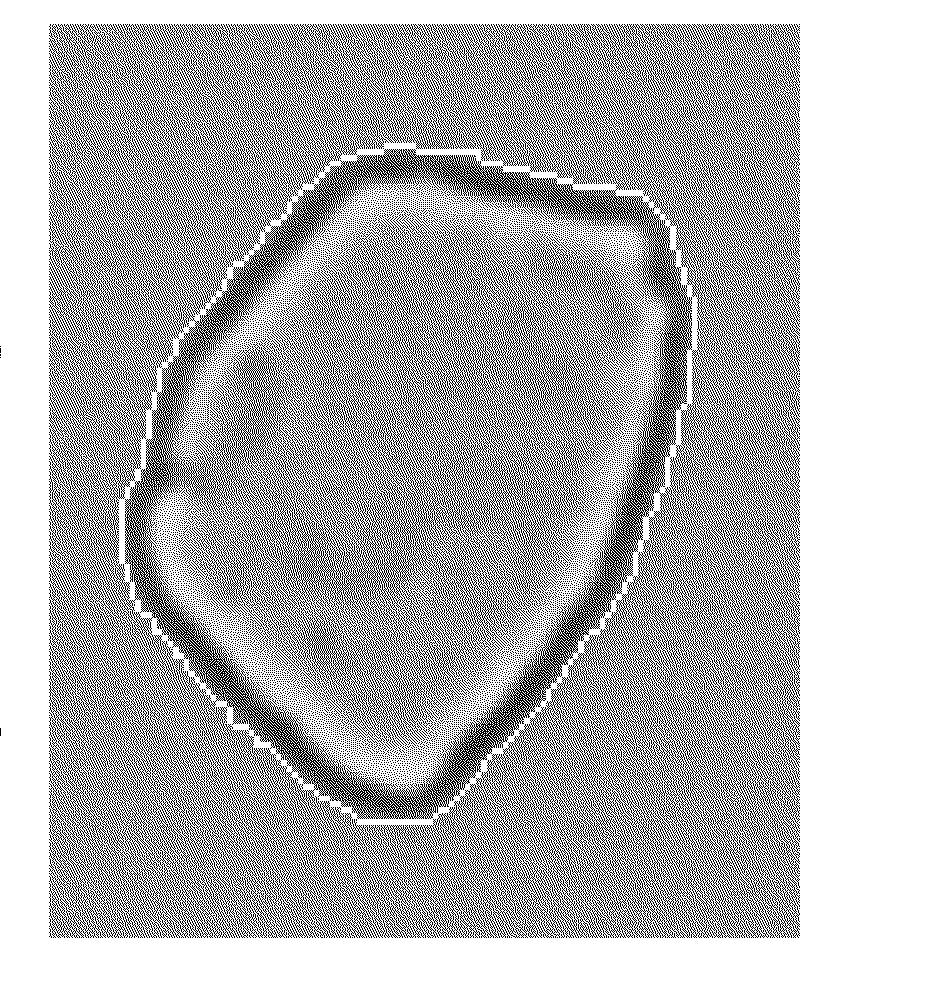
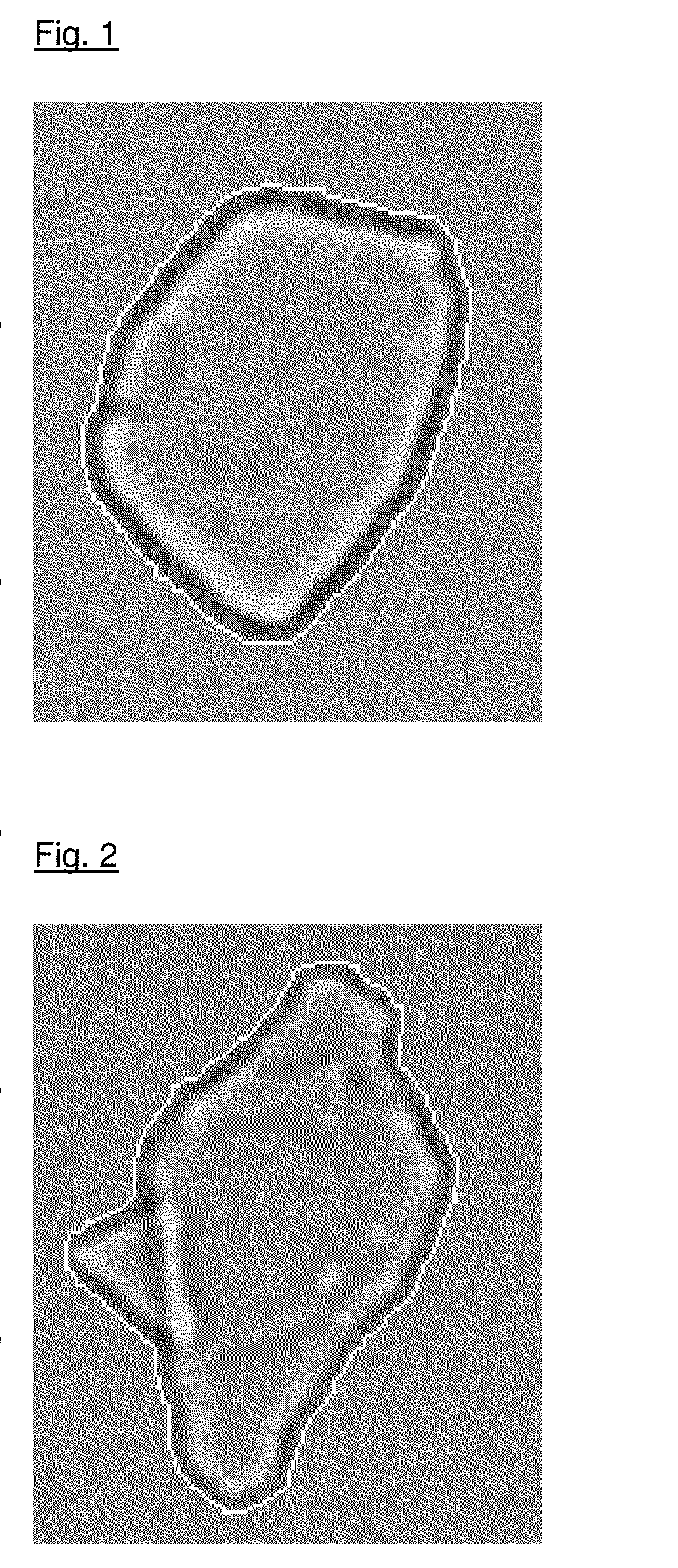
  • Summary
  • Abstract
  • Description
  • Claims
  • Application Information

AI Technical Summary

Benefits of technology

[0005]An object of the present invention is to find effect pigments which have high color saturation and at the same time exhibit a high hiding power without losing their optical properties, in particular the luster and color purity, and are distinguished by advantageous applicational properties.
[0006]Surprisingly, it has now been found that effect pigments based on flake-form substrates which have a roundish shape have increased color saturation and an increased hiding power compared with effect pigments from the prior art based on substrates having an oblong shape with greater edge roughness.
[0019]The additional mechanical treatment and the associated polishing effect produce smoothing of the surface of the substrate particles, with, in addition, the oblong flake shape being converted into a roundish flake shape. The decrease in the circular form factor and the oblong nature is associated with the edges of the substrates becoming smoother and the substrates adopting a rounder shape.

Problems solved by technology

However, effect pigments generally have the disadvantage that they have an inadequate hiding power and inadequate color saturation.

Method used


Image

  • Effect pigments
  • Effect pigments

Examples


example 1a

[0157]1 kg of Muscovite mica, which is in the form of coarse flakes, is ground to a particle size of less than 200 μm by a Koller process. The fine mica flakes formed in this way are introduced into a rotor-stator mill, and 1 l of deionized water is added. The resultant suspension is ground in the mill for 5 hours, during which the surface of the flakes is polished smooth at the same time. The mechanical loading of the particles during the grinding step is selected so that a permanent shear results in further gentle delamination of particles and in smoothing of the edges and surfaces. A narrow particle-size distribution is achieved by a subsequent classification step in the form of a plurality of (at least 3 steps) sedimentation steps. The mica flakes produced in this way have a particle-size distribution of 10-40 μm, a thickness distribution of 0.2 to 0.6 μm (in each case 90% of all particles) and a smooth-polished surface having only few sharp edges. The circular form factor is 1....

example 1 b

[0158]1 kg of synthetic mica flakes is treated analogously to Example 1a. Synthetic mica flakes having a circular form factor of 1.6 are obtained.

II. Coating of the Substrate Flakes

example 2.1

Natural Mica+SnO2+TiO2

[0159]100 g of natural mica flakes from Example 1a are warmed to 75° C. in 2 l of deionized water with stirring. The coating pH of 1.8 is established by dropwise addition of an SnCl4 solution (22 g / l). The remainder of 100 ml of SnCl4 solution (22 g / l) is subsequently metered in. During this addition, the pH is kept constant at 1.8 using 32% sodium hydroxide solution. When the addition is complete, the mixture is stirred for a further 10 minutes.

[0160]At constant pH, 490 ml of a TiOCl2 solution (400 g of TiCl4 / l) are then metered in until the color end point (yellow) has been reached, during which the pH being is constant at 1.8 by simultaneous dropwise addition of 32% sodium hydroxide solution.

[0161]When the addition is complete, the mixture is stirred for a further 10 minutes, the suspension is filtered off with suction and washed with deionized water until salt-free. After drying at 120° C. (24 h), the pigment is calcined at 800° C. for 45 minutes.

[0162]A h...


PUM

PropertyMeasurementUnit
refractive indexaaaaaaaaaa
particle sizeaaaaaaaaaa
diameteraaaaaaaaaa

Abstract

The present invention relates to effect pigments which are based on flake-form substrates having a circular form factor of 1.2-2 and are coated with at least one high-refractive-index layer, and to the use thereof, inter alia in paints, coatings, printing inks, plastics and in cosmetic formulations.

Description

SUMMARY OF INVENTION[0001]The present invention relates to effect pigments which are based on flake-form substrates having a circular form factor of 1.2-2 and are coated with at least one high-refractive-index layer, and to the use thereof, inter alia in paints, coatings, printing inks, plastics, and in cosmetic formulations.[0002]Effect pigments, such as, for example, pearlescent pigments or metal-effect pigments, are employed in many areas of industry, in particular in the area of automotive paints, industrial coatings, decorative coatings, in plastics, in paints, printing inks and in cosmetic formulations. Pigments of this type are based on flake-form oblong substrates with a single or multiple coating.[0003]The size of the base substrates is generally not crucial per se in the case of effect pigments and can be matched to the particular application. In general, the flake-form and oblong substrates have a thickness between 0.1 and 5 μm, in particular between 0.2 and 4.5 μm. The s...

Claims


Application Information

Patent Timeline
Patent Type & Authority Applications(United States)
IPC IPC(8): C09C1/00A23G3/54A23L5/41A61K8/02A61Q3/02A61Q19/10C08K9/02C09D5/36C09D11/037
CPCC09C1/0024A61K8/0258C08K9/02C09D11/037C09C1/0021A61Q19/10A61K2800/436C09D5/36A23G3/54C09C2200/301C09C2200/102C09C2200/1033C01P2004/61A61Q3/02C09C1/0015C09C1/0018C09C1/0039C09C1/0051C09C1/0063C09C1/0066C01P2004/51C01P2006/62C01P2006/63C01P2006/64C01P2006/65C09C2200/1025C09C2200/24C09C2200/302C09C2200/303C09C2200/304C09C2200/306A61Q19/00A61K8/0266A61K2800/412A61K2800/43A23G3/343A23L5/47A23G3/36A23G3/362C09C1/3018C09C3/041C09C1/00C09C3/06
Inventor PFAFF, GERHARDANDES, STEPHANIEAMBROSIUS, KLAUSPETRY, RALFROESLER, MICHAELSCHOEN, SABINE
Owner MERCK PATENT GMBH
Learn More