Light Guide Assembly for an LCD or the Like

a technology of light guide assembly and backlit display, which is applied in the direction of adhesive processes, paper/cardboard containers, instruments, etc., can solve the problems of unacceptably low illumination of the display, time-consuming and laborious assembly process, and difficult to effectively apply the tape to all surface parts, etc., to achieve simple assembly process and robust display

Active Publication Date: 2016-03-03
POLARIS IND INC
View PDF11 Cites 5 Cited by
  • Summary
  • Abstract
  • Description
  • Claims
  • Application Information

AI Technical Summary

Benefits of technology

The present patent is to solve the problem of assembling a display device to a motorcycle and ensuring it is protected against water and dust penetration. The invention provides a method of using an epoxy resin to encapsulate the components and damp vibrations that may come through the casing. This method involves depositing a reflective coating on a surface and installing the display device with the light guide in the interior of the casing. Overall, the invention simplifies the assembly process and protects the light guide from leaking or contamination.

Problems solved by technology

One problem with the epoxy encapsulation technique just mentioned is ensuring that the epoxy does not come into direct contact with the light guide, which may be, for example, formed of optically-clear acrylic.
This absorption reduces the illumination of the display to unacceptably low levels.
This approach, however, is time consuming and requires a labor-intensive assembly process.
Moreover, given the complex shape of some light guides it is difficult to effectively apply the tape to all of the surface portions that may be exposed to contact with the later applied epoxy.

Method used


Image

  • Light Guide Assembly for an LCD or the Like
  • Light Guide Assembly for an LCD or the Like
  • Light Guide Assembly for an LCD or the Like

Examples


Embodiment Construction

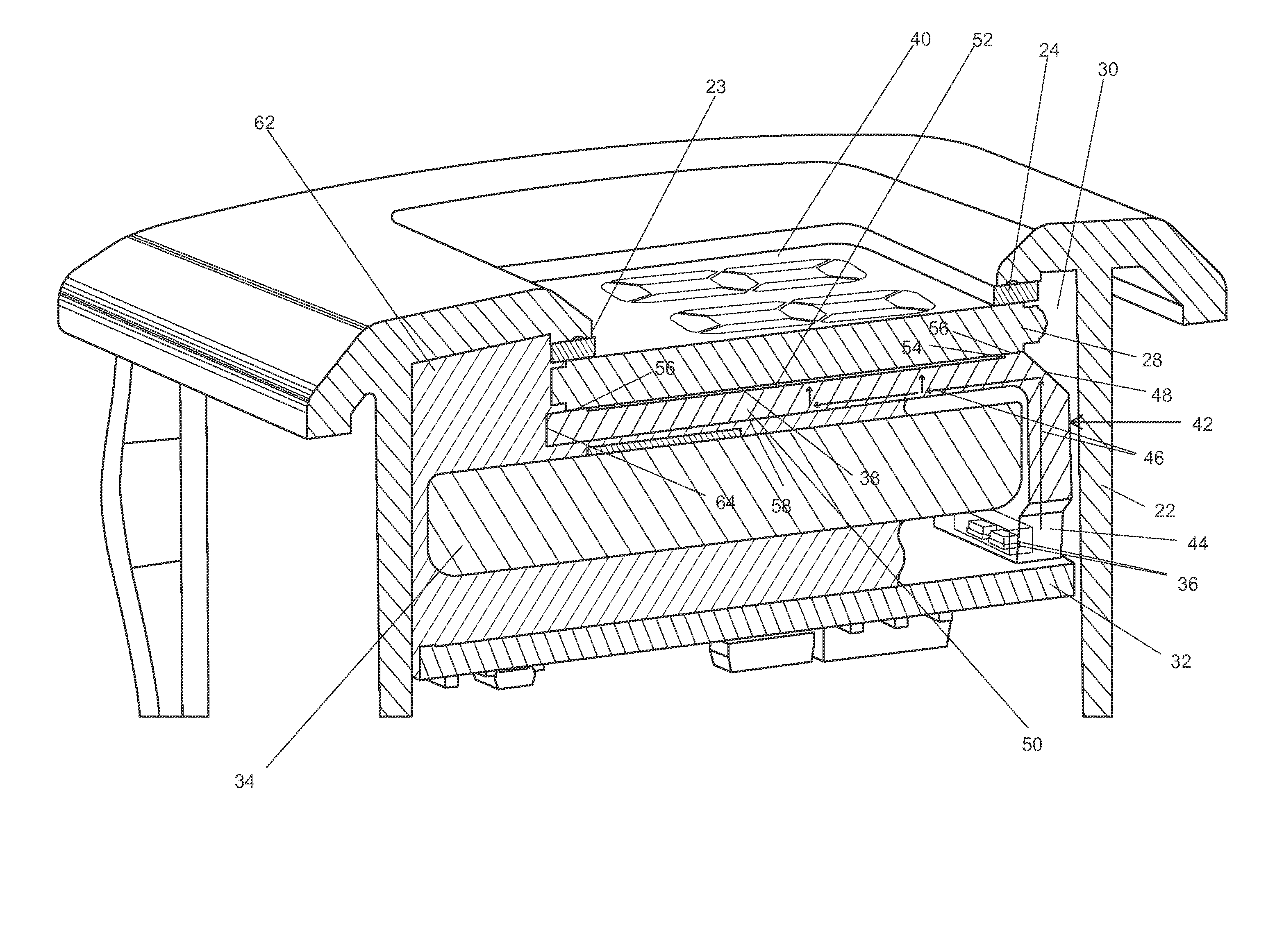
[0016]Shown in FIG. 1 is an exemplary motorcycle meter 20 that includes a display with which the light guide assembly of the present invention may be employed. The meter 20 houses internal components inside of a casing 22, which can be two casing parts attached together. The casing includes an opening 23 on the side of the meter facing the viewer. The meter can include any of a variety of manual control buttons and knobs 26.

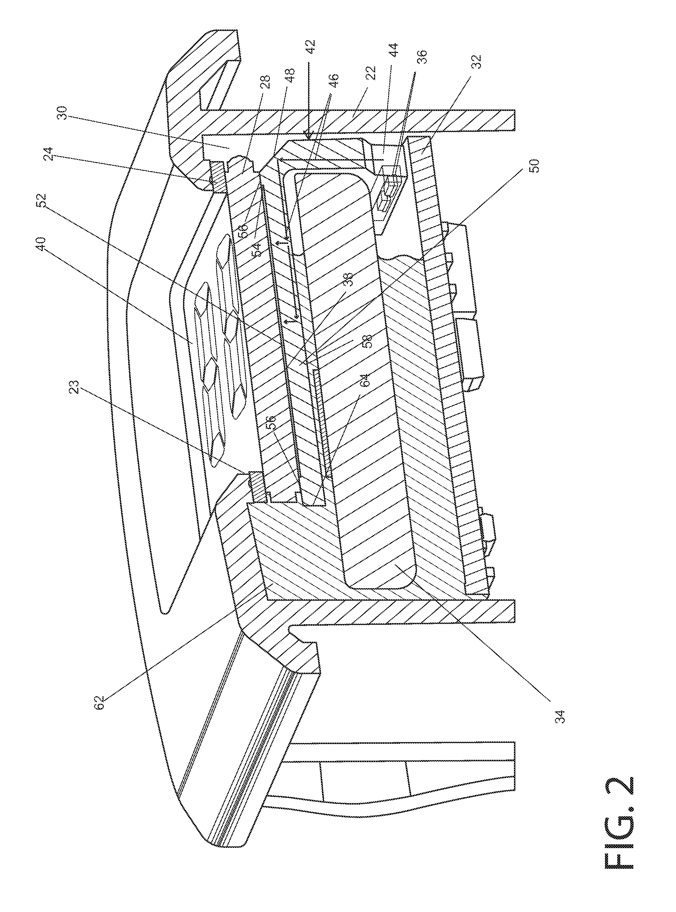
[0017]With reference to FIG. 2, a display device such as a liquid crystal display (LCD) 28 is mounted in the interior space 30 of the casing with the edges of the LCD abutting an opening 23 in the casing. A rectangular gasket 24 is present between the edges of the LCD 28 and the opening 23. Other components of the meter 20 are also carried in this space 30, including the meter's printed circuit board (PCB) 32 with circuit components mounted thereto, as well as a power supply, which in this instance can be a coin cell 34.

[0018]One of the components mounted to the ...


PUM

PropertyMeasurementUnit
temperatureaaaaaaaaaa
transparentaaaaaaaaaa
refraction characteristicsaaaaaaaaaa

Abstract

An apparatus and method for assembling a display device to which is coupled a light guide that has smooth surfaces for light-transmission and at least one surface that is for light scattering and internal reflection. The method includes depositing a reflective coating on that surface, and installing the display device with coupled light guide in an interior of a meter housing or casing. A portion of the casing interior is filled with a component, such as epoxy, for sealing the case interior to protect the display device and light guide against water and dust penetration. All surfaces of the light guide are protected from direct contact with the epoxy. This approach greatly simplifies the assembly process and yields a robust display that also prevents light leakage from the light guide.

Description

FIELD OF THE INVENTION[0001]This invention relates to a backlit display device such as a liquid crystal display (LCD), and in particular to light guide assembly that provides the back light for the display.BACKGROUND AND SUMMARY OF THE INVENTION[0002]Meters used on motorcycles include digital displays of running time (hours), engine temperature and other information. Since the motorcycles may be of the trail-type for traversing rough terrain, the meters must be robust to withstand vibration and shock. The meters must also be well sealed to prevent penetration of fine dust and liquid into the meter.[0003]The meters of interest here include, among other components, a digital LCD that is backlit by light that is provided by a light guide. In this case, the light guide is a transparent glass-like solid through which light propagates from one end of the guide to another. The light guide is coupled to the display and transmits light from a source, such as one or more light emitting diodes...

Claims


Application Information

Patent Timeline
Patent Type & Authority Applications(United States)
IPC IPC(8): F21V8/00B62J6/00
CPCG02B6/0036G02B6/0065B62J2300/0026B62J6/00G02B6/0093B62J50/22G02B6/0088
Inventor CHAMBERS, TRAVISLARSON, JUSTIN
Owner POLARIS IND INC
Why Eureka
Try Eureka