
Drive control circuit, and ignition device for internal combustion engine

a control circuit and control circuit technology, applied in the direction of process and machine control, pulse technique, instruments, etc., can solve the problems of difficult to embed bypass capacitors in control circuits, degrade noise resistance, etc., and achieve the effect of reducing noise resistance and more reliable protection

Inactive Publication Date: 2016-03-03
DENSO CORP
View PDF3 Cites 1 Cited by
  • Summary
  • Abstract
  • Description
  • Claims
  • Application Information

AI Technical Summary

Benefits of technology

The patent is about a protection circuit that uses a diode to protect a control circuit from negative surge and AC noise. However, during a more severe noise test, the voltage levels of the ignition signal input at binary levels increased in the control circuit, which may decrease the noise resistance. The inventors found that a clamping function is needed to protect against both negative and positive surges. They designed a protection circuit that uses Zener diodes and a capacitive element to improve the positive-negative asymmetry of the waveform of the noise and reduce the magnitude of the mean voltage of the AC noise. This results in higher noise resistance and reduces fluctuations in the voltage level of the input signal due to the AC noise. The patent also mentions that the circuit can protect the capacitive element from high-frequency surges resulting from ESD or the like. Overall, the patent proposes an improved protection circuit to safeguard the control circuit from surges and noise.

Problems solved by technology

If the levels of the ignition signal wholly increase, margins relative to a threshold voltage when a comparator determines the levels of the ignition signal (particularly the margin relative to the L level) may decrease to possibly degrade noise resistance.
However, the capacitive value of the bypass capacitor provided for such a purpose is extremely large (e.g., several microfarads) so that it is difficult to embed the bypass capacitor in the control IC.

Method used


Image

  • Drive control circuit, and ignition device for internal combustion engine
  • Drive control circuit, and ignition device for internal combustion engine
  • Drive control circuit, and ignition device for internal combustion engine

Examples


first embodiment

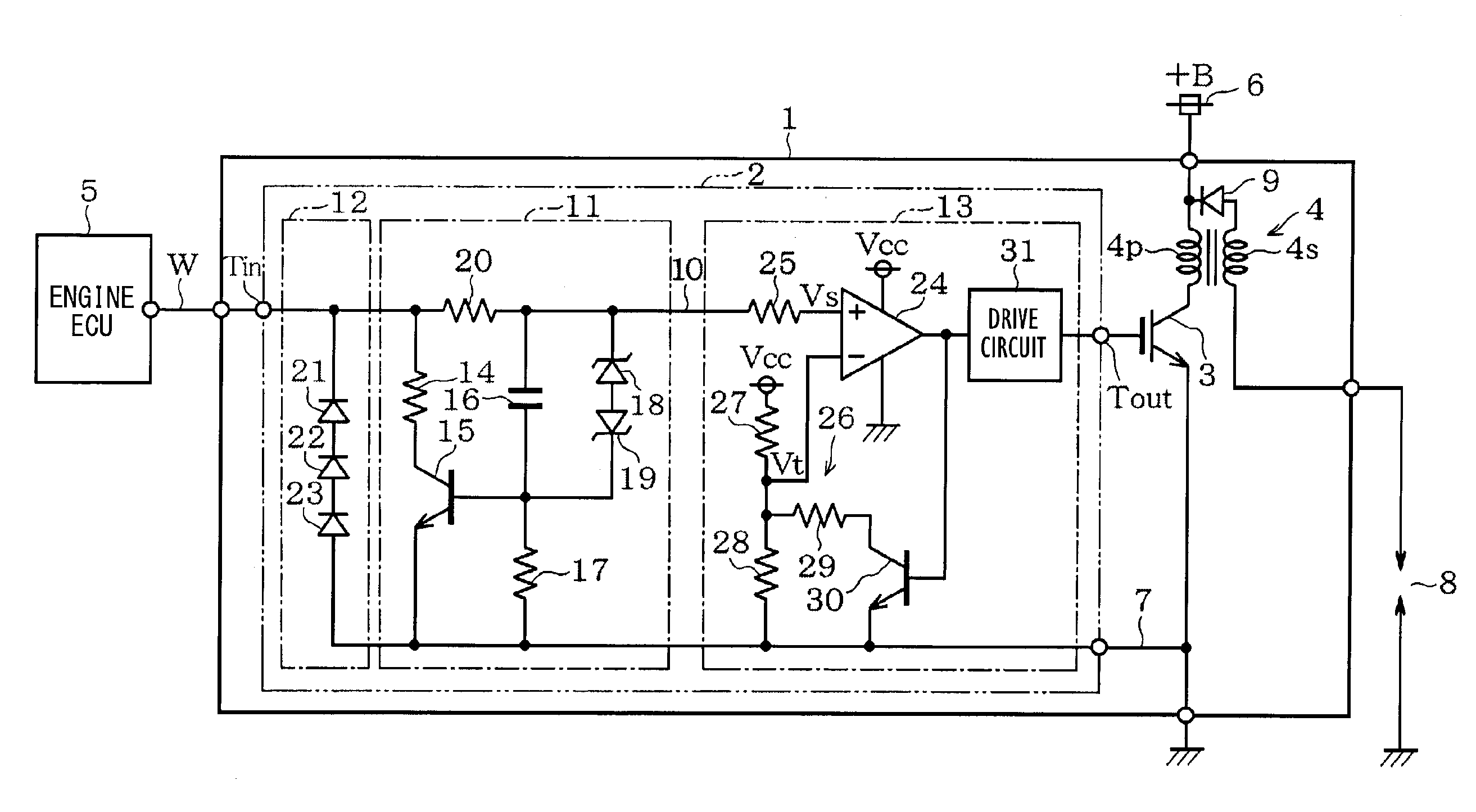
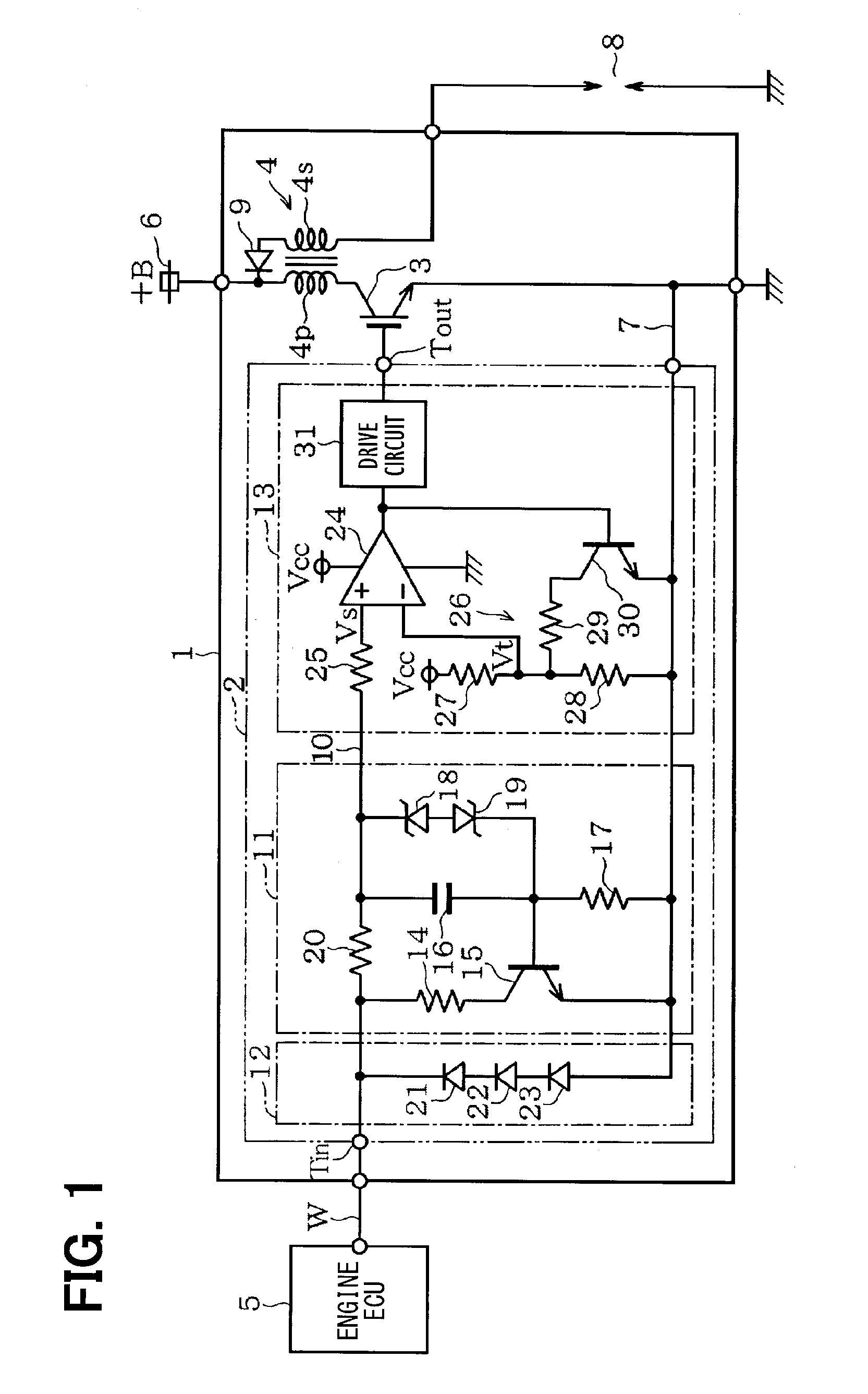
[0039]The following will describe the first embodiment of the present disclosure with reference to FIGS. 1 to 3C. An ignition device (i.e., an ignition device for an internal combustion engine) shown in FIG. 1 includes a control IC 2, an IGBT 3, and an ignition coil 4. The control IC 2 is a drive control circuit that outputs a drive signal (i.e., a gate signal) for driving the IGBT 3 to turn on or off in response to an ignition signal (i.e., an input signal) sent from an engine ECU 5 through a wire line W.

[0040]The IGBT 3 is a switching element for applying or interrupting current flow in the ignition coil 4 (i.e., a load), which is provided separately from the control IC 2. Between a power supply line 6 to which a battery voltage +B is supplied and a ground line 7, a primary coil 4p of the ignition coil 4 and a part between the collector and the emitter of the IGBT3 are connected in series. A secondary coil 4s of the ignition coil 4 is connected to a plug 8. A diode 9 is connected ...

second embodiment

[0064]An ignition device 41 shown in FIG. 4 is different from the ignition device 1 shown in FIG. 1 only in the configuration of a positive noise protection circuit 43 of a control IC 42. That is, in the positive noise protection circuit 43, a resistor 44 and the capacitor 16 are connected in series between the collector and base of the transistor 15 and, from the signal input line 10, the resistor 20 has been removed. To the capacitor 16, the Zener diodes 18 and 19 connected in series are connected in parallel.

[0065]In this configuration also, the capacitor 16 is connected between the signal input line 10 and the base of the transistor 15 through the resistors 14 and 44. The configuration of the positive noise protection circuit 43 is otherwise the same as that of the positive noise protection circuit 11. The resistors 14 and 44 serve as adjustment elements for a base current and a collector current in the transistor 15. From the present embodiment also, the same function and effec...

third embodiment

[0066]An ignition device 51 shown in FIG. 5 is different from the ignition device 1 shown in FIG. 1 in the configurations of a positive noise protection circuit 53 and a negative noise protection circuit 54 of a control IC 52. The positive noise protection circuit 53 has the configuration in which, between the signal input line 10 and the ground line 7, a diode 55 having an anode connected to the signal input line 10 and a Zener diode 56 having a cathode connected to the signal input line 10 are connected in series. The negative noise protection circuit 54 has the configuration in which, between the signal input line 10 and the ground line 7, a diode 57 having a cathode connected to the signal input line 10 and a Zener diode 58 having an anode connected to the signal input line 10 are connected in series.

[0067]The clamp level +Vp of the positive noise protection circuit 53 results in a voltage obtained by adding a forward voltage Vf of the diode 55 to the Zener voltage of the Zener ...


PUM


Abstract

A drive control circuit includes: a first protection circuit connected between a signal input line and a ground line and clamps a voltage of AC noise superimposed on the signal input line at one clamp level; a second protection circuit connected between the signal input line and the ground line and clamps the voltage of the AC noise superimposed on the signal input line at an other clamp level Vn; and a drive signal generation circuit generating the drive signal based on a comparison between a voltage in the signal input line and Vt. The input signal has binary levels including an L-level voltage VL and an H-level voltage VH, and a mean voltage of the AC noise is lower than a differential voltage between Vt and VL and higher than a differential voltage between Vt and VH.

Description

CROSS REFERENCE TO RELATED APPLICATION[0001]This application is based on Japanese Patent Application No. 2013-85720 filed on Apr. 16, 2013, the disclosure of which is incorporated herein by reference.TECHNICAL FIELD[0002]The present disclosure relates to a drive control circuit that generates a drive signal for a switching element for performing one of the conduction and cut-off of current flow in a load; and an ignition device for an internal combustion engine.BACKGROUND ART[0003]The ignition device for an internal combustion engine (hereinafter referred to as the ignition device) disclosed in Patent Literature 1 or the like has been increasingly reduced in size. This type of ignition device includes: a switching element applying or interrupting current flow in an ignition coil (i.e., load); and a control IC driving the switching element to turn on or off in response to an ignition signal (i.e., input signal) as a rectangular wave inputted from an engine ECU (i.e., electronic contr...

Claims


Application Information

Patent Timeline
Patent Type & Authority Applications(United States)
IPC IPC(8): F02P3/055F02P7/077H03K17/567
CPCF02P3/0435H03K17/567F02P7/077F02P3/055
Inventor YAMAGUCHI, MOTOO
Owner DENSO CORP
Learn More