Fuel injection control device and fuel injection system
a control device and fuel injection technology, applied in the direction of fuel injecting pumps, electric control, machines/engines, etc., can solve the problems of fuel having a small spray particle diameter, fuel cannot be injected, and the supply fuel pressure needs to be decreased, so as to prevent the energy required for the drive of the high-pressure pump from becoming unnecessarily large, the spray particle diameter is small, and the effect of reducing the energy consumption
- Summary
- Abstract
- Description
- Claims
- Application Information
AI Technical Summary
Benefits of technology
Problems solved by technology
Method used
Image
Examples
first embodiment
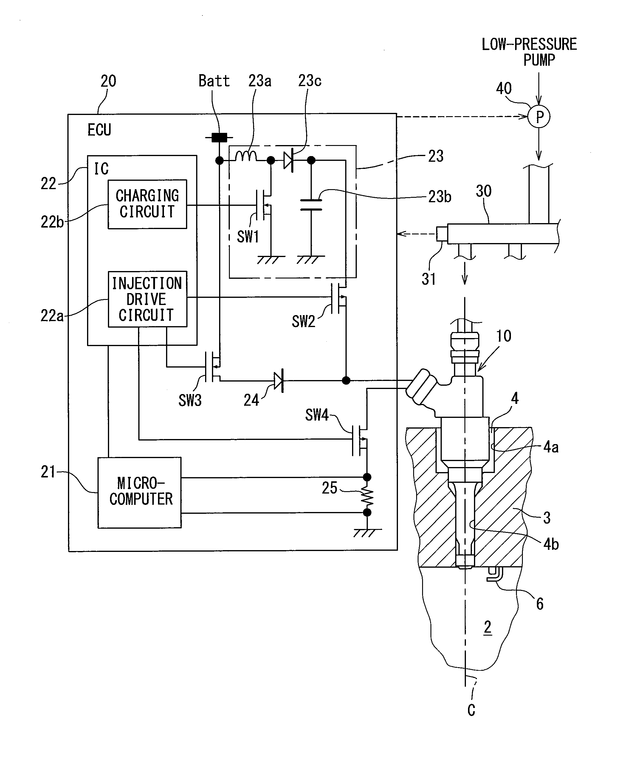
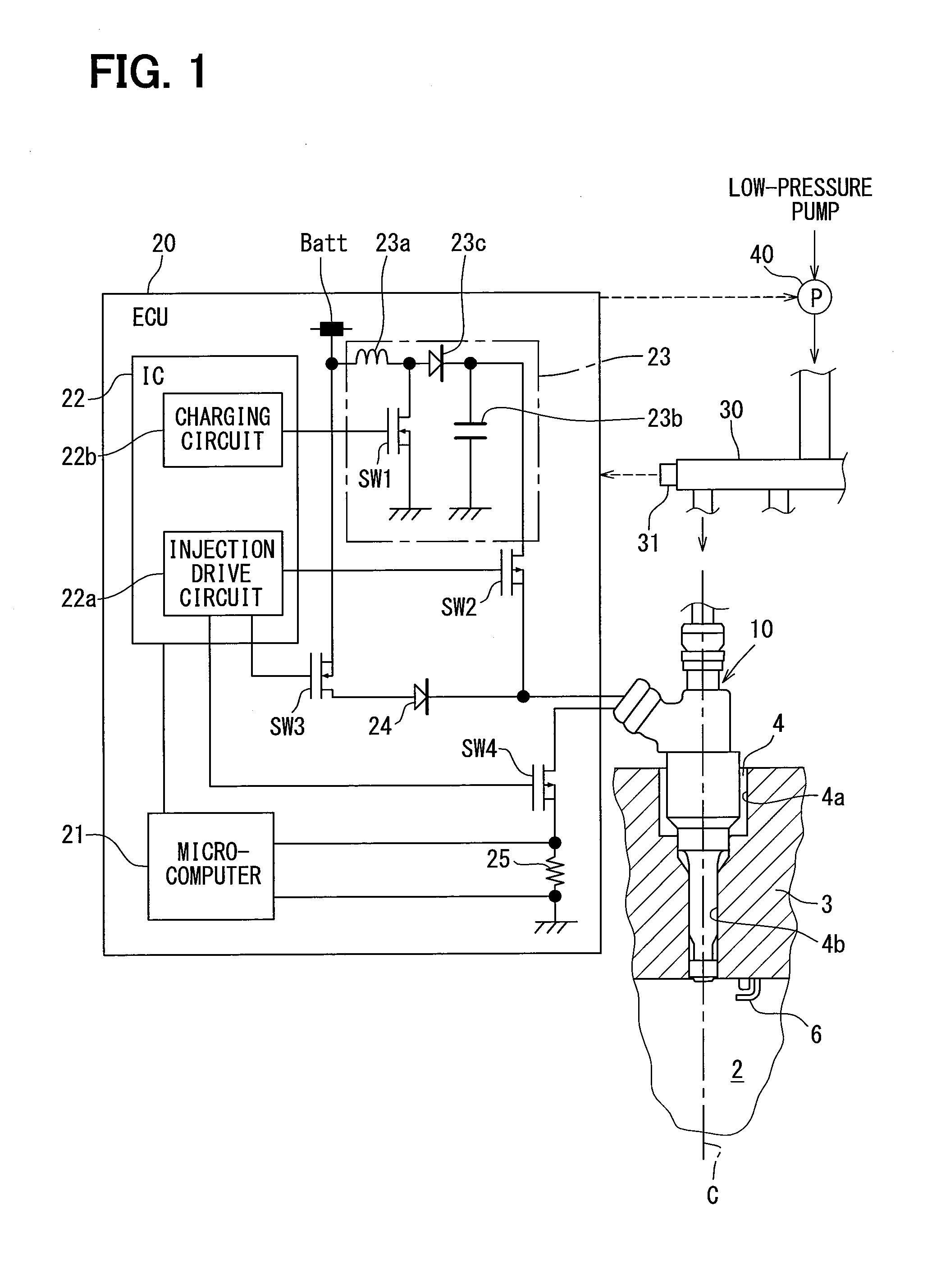
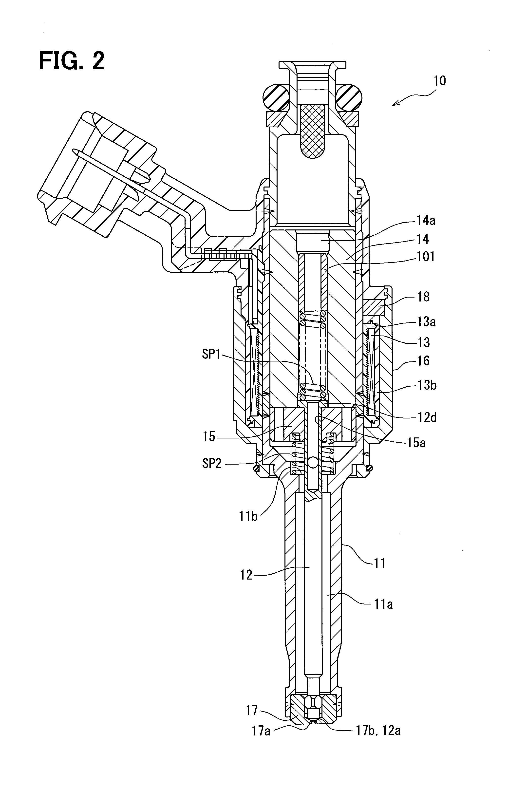
[0036]An injector 10 illustrated in FIG. 1 is disposed in an ignition-type internal combustion engine (gasoline engine) to inject fuel directly into a combustion chamber 2 of the engine. Specifically, an attachment hole 4, into which the injector 10 is inserted, is formed at a position of a cylinder head 3 defining the combustion chamber 2 that accords with an axis C of a cylinder.
[0037]The fuel supplied to the injector 10 is stored in a fuel tank (not shown). The fuel in the fuel tank is pumped up by a low-pressure pump, and is pressure-fed into a delivery pipe 30 with its pressure raised by a high-pressure pump 40. The high-pressure fuel in the delivery pipe 30 is distributed and supplied to an injector 10 of each cylinder. Structure of the high-pressure pump 40 will be described later in detail in reference to FIG. 5.
[0038]An ignition plug 6 is attached to the cylinder head 3. The ignition plug 6 and the injector 10 are arranged side by side at parts of the cylinder head 3 that a...
second embodiment
[0121]In the above first embodiment, at S11 in FIG. 8, the output improved amount and the pump loss amount are calculated, and it is determined whether the inequation: output improved amount>pump loss amount is satisfied based on this calculation result. In the present embodiment, at the time of starting of the engine, the output improved amount and the pump loss amount are not calculated, and the full lift injection is chosen with the output improved amount considered to be smaller than the pump loss amount.
[0122]The “time of starting” in this case means the time while the engine is driven by a starter motor. At such starting time, it is highly probable that the output improved amount is larger than the pump loss amount. Accordingly, in the present embodiment, a processing load of a microcomputer 21 which calculates the output improved amount and the pump loss amount is reduced, and the control which performs the full lift injection in the case of output improved amount<pump loss a...
third embodiment
[0123]In the above first embodiment, at S10 in FIG. 8, a small-large comparison is made between the partial maximum injection quantity Qplmax and the required injection quantity Qreq, and based on this comparison result, it is determined whether the partial injection is carried out. In the present embodiment, when the engine is in idle operation, the small-large comparison between Qplmax and Qreq is not made, and the partial injection is chosen with the required injection quantity Qreq considered to be equal to or smaller than the partial maximum injection quantity Qplmax.
[0124]At such time of idle operation, it is highly probable that the required injection quantity Qreq is equal to or smaller than the partial maximum injection quantity Qplmax. For this reason, in the present embodiment, a processing load of a microcomputer 21 which makes the small-large comparison between Qplmax and Qreq can be reduced, and control can be performed to carry out the partial injection in the case of...
PUM
 Abstract
Description
Claims
Application Information
 - Generate Ideas
- Intellectual Property
- Life Sciences
- Materials
- Tech Scout
- Unparalleled Data Quality
- Higher Quality Content
- 60% Fewer Hallucinations
Browse by: Latest US Patents, China's latest patents, Technical Efficacy Thesaurus, Application Domain, Technology Topic, Popular Technical Reports.
© 2025 PatSnap. All rights reserved.Legal|Privacy policy|Modern Slavery Act Transparency Statement|Sitemap|About US| Contact US: help@patsnap.com


