Microrelief structural body, decorative sheet, decorative resin molded body, method for producing microrelief structural body, and method for producing decorative resin molded body

Active Publication Date: 2016-02-25
MITSUBISHI CHEM CORP
View PDF1 Cites 20 Cited by
  • Summary
  • Abstract
  • Description
  • Claims
  • Application Information

AI Technical Summary

Benefits of technology

The present invention provides a decorative sheet with a microrelief structure layer that can be used for three-dimensional molding without compromising its antireflection performance. The microrelief structural body is made of a curable composition that has a high degree of flexibility and can be easily integrated into a complex-shaped body. The decorative sheet has excellent moldability and can be easily produced using a mold. The technical effect of this invention is to expand the design options and improve the appearance of three-dimensional molded bodies.

Problems solved by technology

In applications for which reduction of background reflections is desirable, such as displays and lenses, various antireflective technologies have been applied; however, there is a problem that deployment of such technologies on curved surfaces or complicated shapes is difficult.
Regarding related art technologies, there is known a technology of preventing reflection by subjecting surfaces of final manufactured products to a multilayer coating obtained by laminating a high refractive index resin and a low refractive index resin; however, it is very difficult to apply this antireflective technology based on multilayer coating to curved surfaces or complicated shapes.
However, it is not easy to obtain antireflection performance by providing the aforementioned microrelief structure on the surface of a manufactured product having a complicated shape, and there is also a problem in view of production cost.
The antireflective film with multilayer coating described above exhibits antireflection performance by precisely controlling the refractive indices and thicknesses of various layers, and therefore, when such a film is used in three-dimensional molding such as insert molding or press molding, there is a problem that the intrinsic antireflection performance cannot be sufficiently exhibited.
In these methods described in Patent Documents 1 and 2, an intended microrelief structure can be provided to a molded body by providing a reverse structure of a microrelief structure in the mold; however, it is difficult to form a reverse structure of an intended microrelief structure in the mold, and since it is a premise that a molten resin that can be injection molded is used, it is very difficult to impart functions other than the antireflection performance.
Furthermore, in a case in which the microrelief structure described above is used for three-dimensional molding, the microrelief structure has inferior scratch resistance compared to molded bodies such as a hard coat having smooth surface that has been produced using the same curable composition, and therefore, a molded body laminated with the microrelief structure has a problem with durability during use.
That is, in a case in which a cured product of an active energy ray-curable composition used for the production of a microrelief structure is not sufficiently solid, there occurs a phenomenon in which convexities of micro-concavo-convex shapes draw close together as a result of release from the template or heating, and as a result, there is a problem that the antireflection performance is deteriorated.
However, such a curable composition gives a cured product that lacks “elongation”, that is, lacks “stretchability”.
Therefore, it is impossible to perform the three-dimensional molding previously mentioned.
When a microrelief structural body is formed using a curable composition which can give a cured product having excellent flexibility and stretchability, it is possible to use the microrelief structural body for three-dimensional molding; however, the phenomenon in which convexities draw close together occurs, and the antireflection performance is impaired.

Method used


Image

  • Microrelief structural body, decorative sheet, decorative resin molded body, method for producing microrelief structural body, and method for producing decorative resin molded body
  • Microrelief structural body, decorative sheet, decorative resin molded body, method for producing microrelief structural body, and method for producing decorative resin molded body
  • Microrelief structural body, decorative sheet, decorative resin molded body, method for producing microrelief structural body, and method for producing decorative resin molded body

Examples


first embodiment

of Microrelief Structural Body Having Physical Properties Described Above

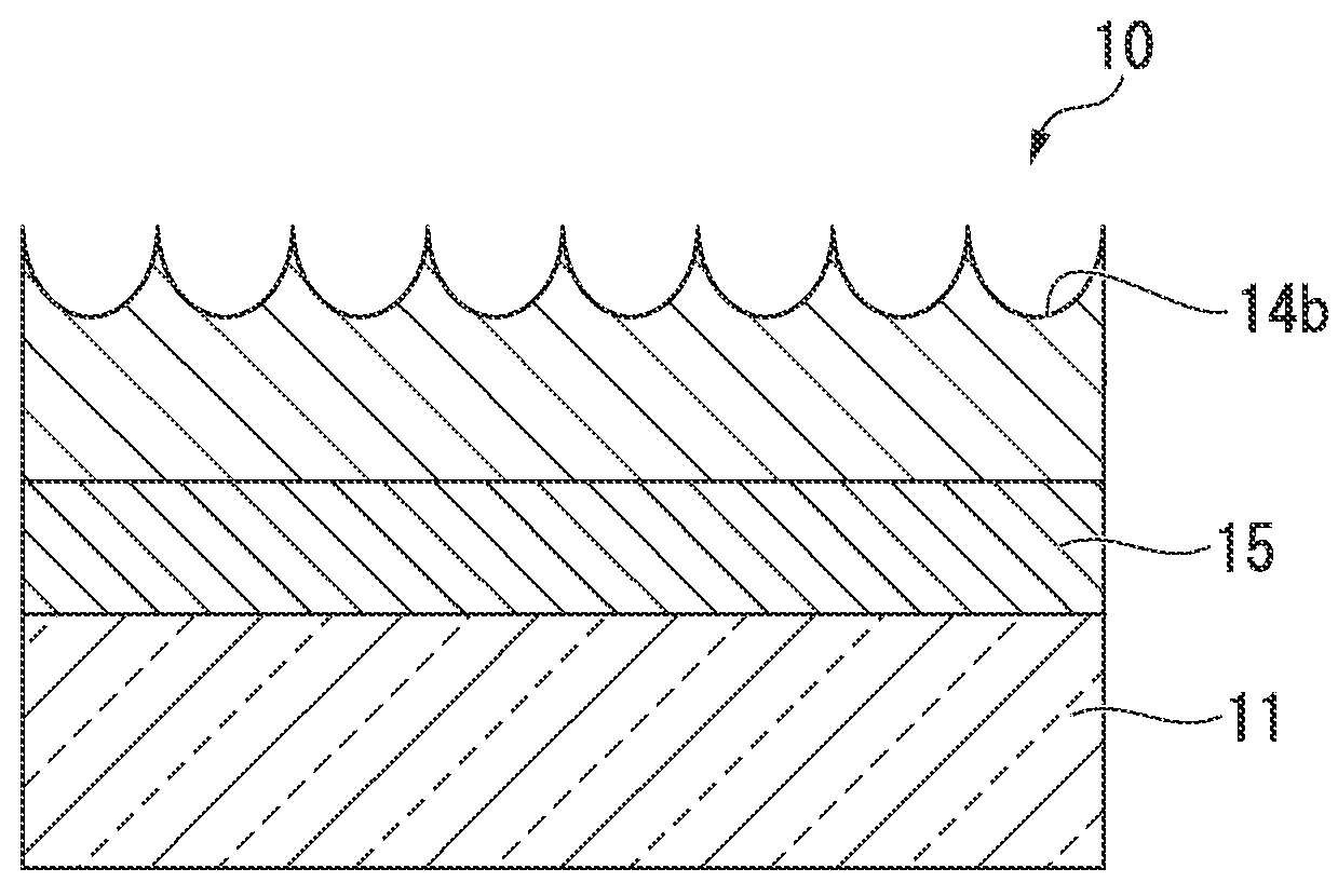
[0140]An example of the microrelief structural body having the physical properties is the microrelief structural body 10 (that is, microrelief structural layer) including a base material 11 and a cured product 12 having microconcavities 14 on the surface, as illustrated in FIG. 1A and FIG. 1B. The microrelief structural body having the physical properties may also have an intermediate layer 15 illustrated in FIG. 1A and FIG. 1B. That is, the microrelief structural body having the physical properties is, for example, a structural body including a base material and a microrelief structural layer having a microrelief structure, in which the microrelief structural layer is laminated on the base material as a surface layer.

[0141]Furthermore, the structural body may also be a structural body including a base material, an intermediate layer, and a microrelief structural layer having a microrelief structure, in which t...

second embodiment

of Microrelief Structural Body Having Physical Properties Described Above

[0215]An example of the microrelief structural body having the physical properties described above is a microrelief structural body 10 in which a cured product 12 of the curable composition according to the present invention is laminated on a base material 11, with a below-described intermediate layer 15 interposed therebetween, as illustrated in FIG. 5A and FIG. 5B.

[0216]That is, an example of the microrelief structural body having the physical properties is a structural body including a base material, an intermediate layer, and a microrelief structural layer having a microrelief structure, in which the microrelief structural layer is laminated on the base material as a surface layer of the structural body, with the intermediate layer interposed there between.

[0217](Microrelief Structure)

[0218]The surface of the cured product 12 has a microrelief structure. The microrelief structure is formed such that, for ex...

examples

[0386]Hereinafter, the present invention will be specifically described by way of Examples. In the following description, unless particularly stated otherwise, the unit “parts” means “parts by mass”. Also, various methods for measurement and evaluation are as follows.

[0387](1) Measurement of Protrusions of Mold:

[0388]A mold having a microconvexity structure that was obtained by transfer from a mother mold formed of anodized porous alumina, was subjected to Pt vapor deposition for one minute on a portion of a vertical cross-section, and the cross-section was observed with a field emission type scanning electron microscope (manufactured by JEOL, Ltd., trade name: JSM-7400F) at an accelerating voltage of 3.00 kV. Thus, the interval (period) of adjoining convexities and the height of the convexities were measured. Specifically, measurements were made at 10 sites for each item, and the average value thereof was designated as the measured value.

[0389](2) Measurement of Concavities of Micr...


PUM

PropertyMeasurementUnit
Temperatureaaaaaaaaaa
Percent by massaaaaaaaaaa

Abstract

A structural body which comprises a base and a microrelief structure layer having a microrelief structure. The microrelief structure layer is laminated on the base so as to form the surface layer of this structural body, and the microrelief structure layer has at least one physical property selected from the group consisting of (A) and (B) described below. (A) The elastic modulus at 25° C. is 50 MPa or more, and the elastic modulus at 80° C. is 30 MPa or less. (B) The tensile elongation at break at 80° C. is from 20% to 100% (inclusive).

Description

TECHNICAL FIELD[0001]The present invention relates to a microrelief structural body having excellent antireflection performance and being moldable by three-dimensionally molding such as insert molding or in-mold lamination, a decorative sheet, a decorative resin molded body, and a curable composition for forming the microrelief structural body. The invention also relates to a method for producing a microrelief structural body having excellent antireflection performance and being moldable by three-dimensional molding, and a method for producing a decorative resin molded body.[0002]The present patent application claims priority based on Japanese Patent Application No. 2013-079743 filed in Japan on Apr. 5, 2013, and Japanese Patent Application No. 2014-031730 filed in Japan on Feb. 21, 2014, the disclosures of which are incorporated herein by reference.BACKGROUND ART[0003]In fields where higher design characteristics are required, such as light covers and front face plates of various d...

Claims


Application Information

Patent Timeline
IPC IPC(8): B32B3/30B29C33/42B29C45/16B29C51/02B32B27/08B32B27/30B32B27/36
CPCB32B3/30B29K2033/04B32B27/304B32B27/308B32B27/365B29C51/02B29C45/1679B29C33/424B32B2307/51B32B2451/00B32B2307/54B29K2995/0093B29L2031/756B29K2995/0024B29K2105/256B29K2069/00B32B27/08B29C37/0032B29C45/1418B29C51/14B29C2037/0042B32B27/06B32B27/36B32B2307/408B32B2307/738G02B1/118
Inventor TAKIHARA, TSUYOSHIOKAMOTO, EIKO
Owner MITSUBISHI CHEM CORP
Why Eureka
Try Eureka