Eureka AIR delivers breakthrough ideas for toughest innovation challenges, trusted by R&D personnel around the world.

Semi-automatic pistol

a semi-automatic, pistol technology, applied in the field of semi-automatic pistols, can solve the problems of increased torque on the shooter's wrist, difficult for the user to keep the model 1911 on target for follow-up shots, and the inability to eliminate the coil, etc., to achieve the effect of better appreciation of the contribution to the ar

Active Publication Date: 2016-02-18
DANIELD DEFENSE LLC
View PDF3 Cites 30 Cited by
  • Summary
  • Abstract
  • Description
  • Claims
  • Application Information

AI Technical Summary

Benefits of technology

The present invention is an improved semi-automatic pistol that has the advantageous features of previous designs. It includes a frame, a barrel, a slide, a recoil mechanism, and a trigger guard. The recoil mechanism is positioned below the barrel and forward of the trigger finger space. The recoil mechanism may be a recoil spring or a helical shape guide rod. The trigger guard has a downwardly facing surface that defines the trigger finger space. The invention aims to provide an improved pistol that overcomes the disadvantages of previous designs and meets the needs of users.

Problems solved by technology

The rotation of the pistol resulting from an initial shot delays subsequent shots because the shooter has to expend time adjusting the pistol to reacquire the target prior to firing each follow-up shot.
While various attempts have been made to control recoil to reduce firearm movement, recoil is considered the best mechanism for feeding semi-automatic firearms, so recoil elimination is not necessarily desirable.
However, the Model 1911 suffers from the disadvantage of all prior art pistols in that the placement of the recoil mechanism at such a distance above the shooter's wrist contributes to greater torque about the shooter's wrist, making it difficult for the user to continuously keep the Model 1911 on target for follow-up shots.
The placement of the recoil mechanism at such a distance above the shooter's wrist contributes to greater torque about the shooter's wrist, making it difficult for the user to continuously keep Moon's firearm on target for follow-up shots.

Method used


Image

  • Semi-automatic pistol
  • Semi-automatic pistol
  • Semi-automatic pistol

Examples


Embodiment Construction

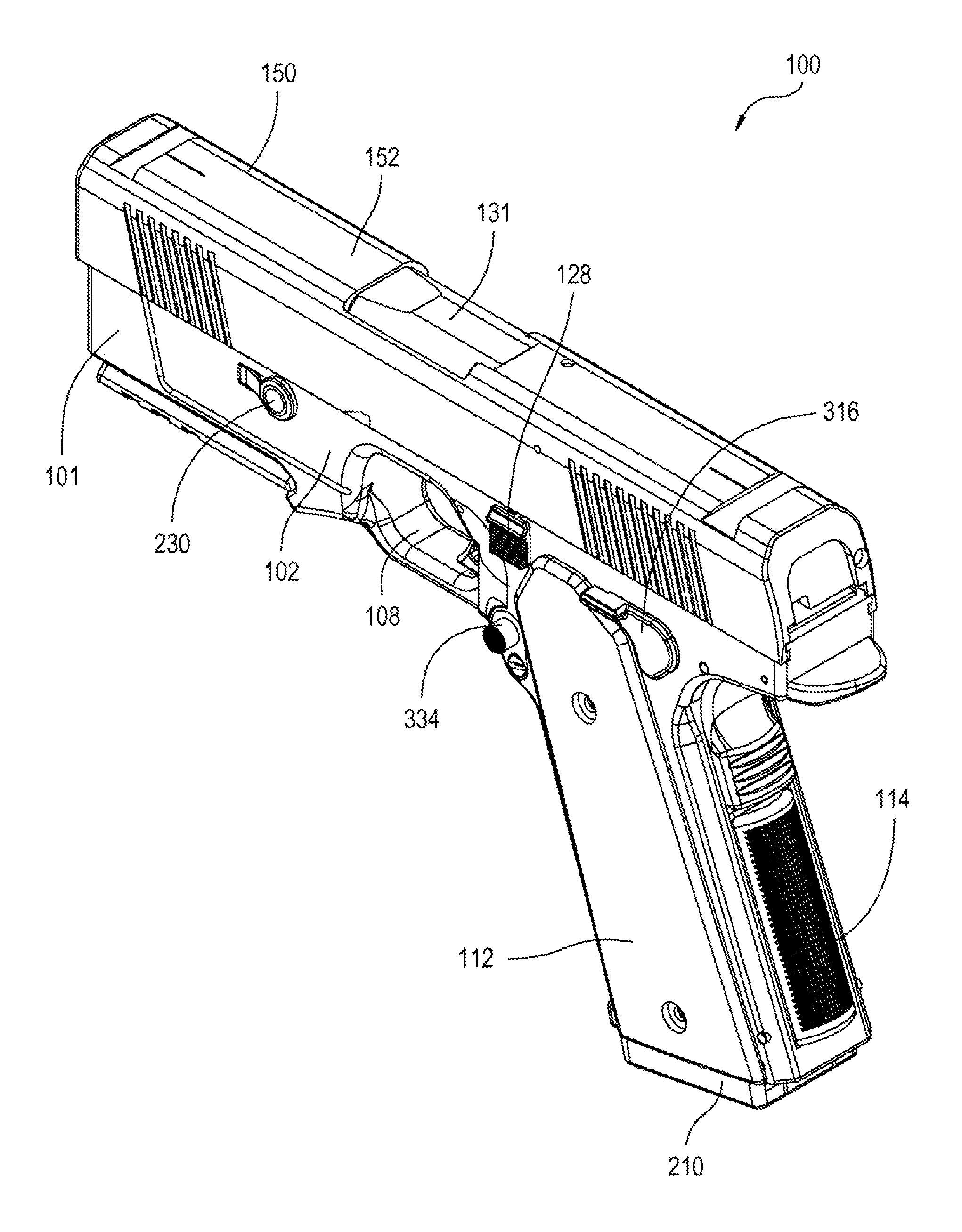
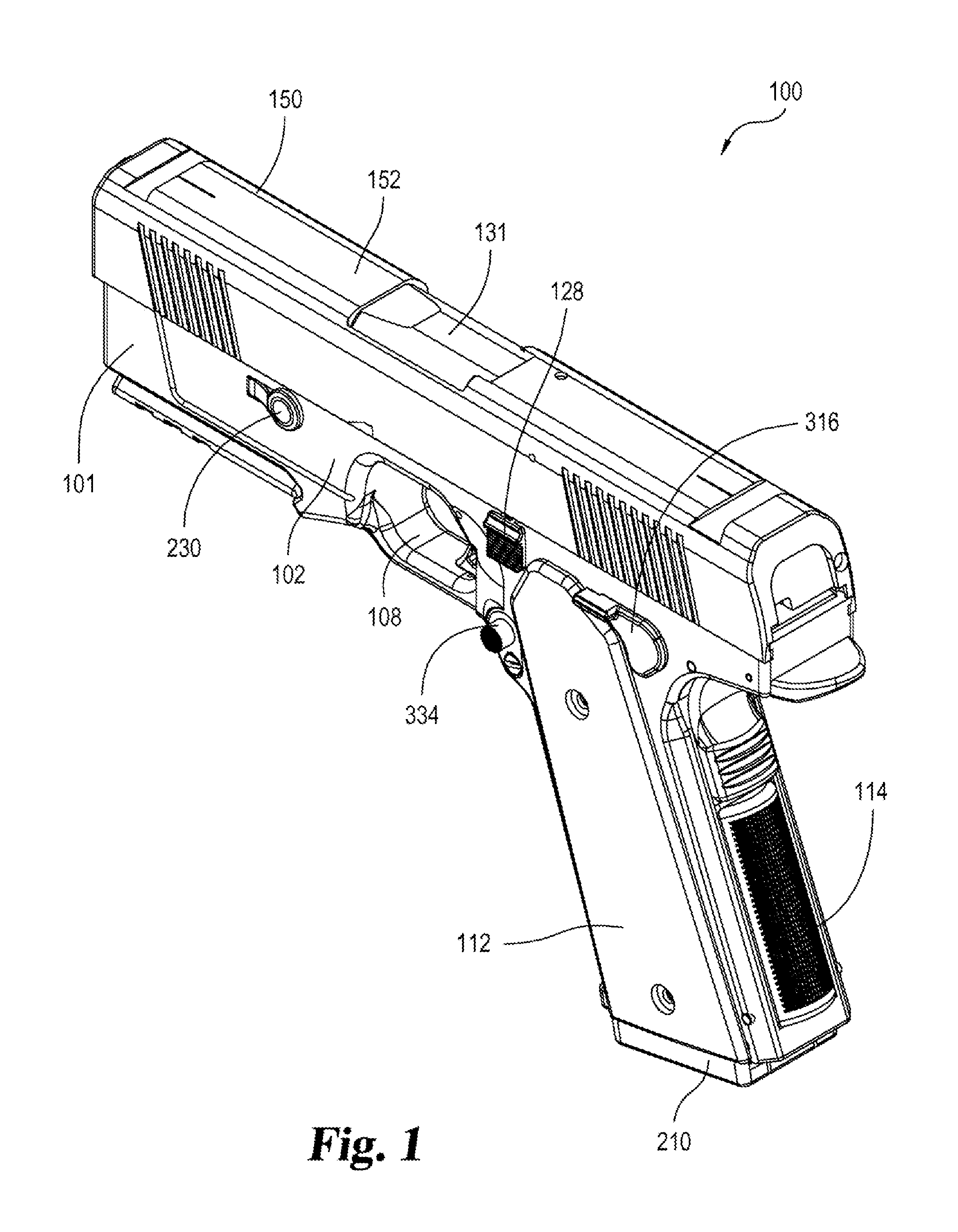
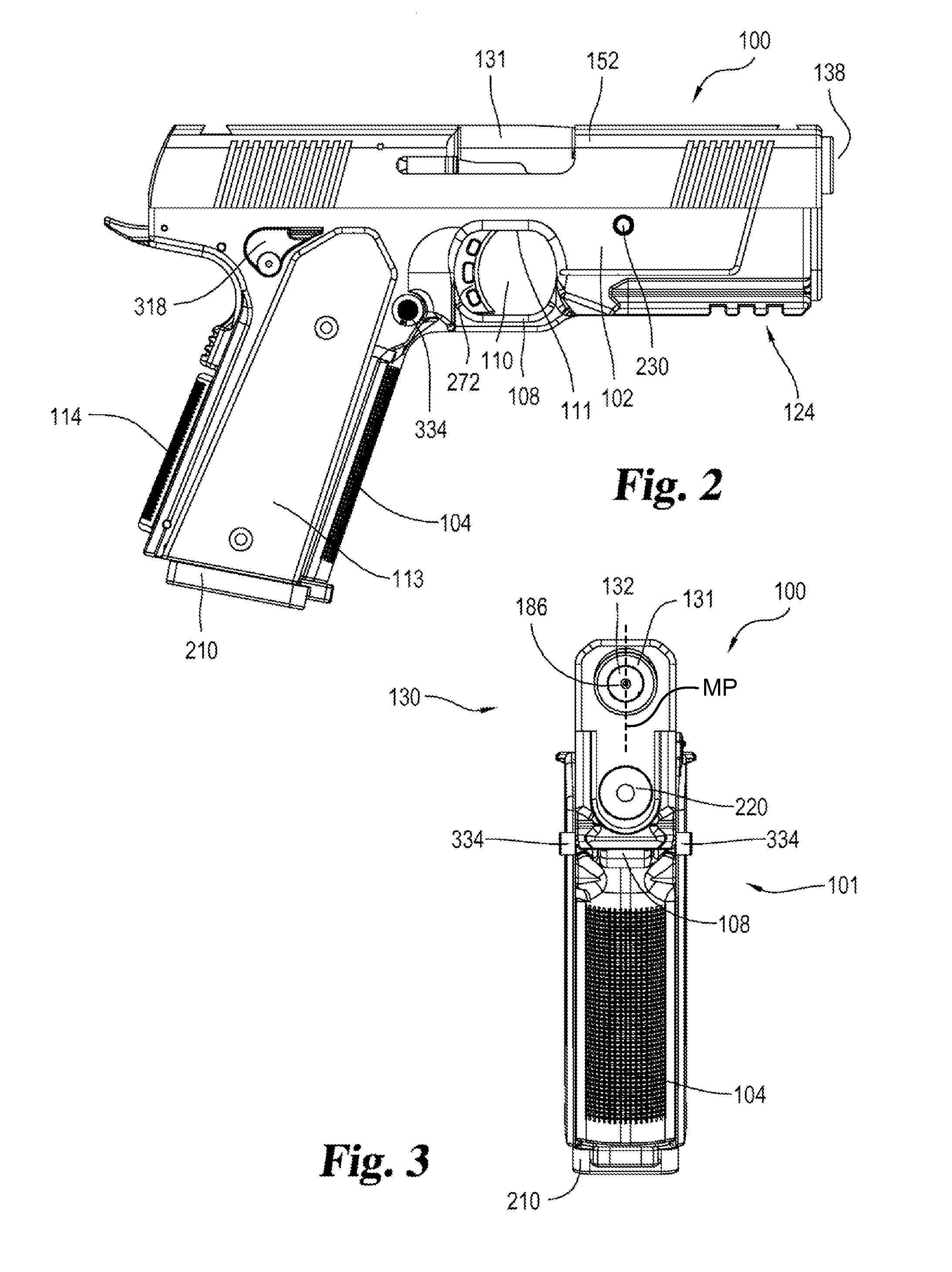
[0066]An embodiment of the semi-automatic pistol of the present invention is shown and generally designated by the reference numeral 100.

[0067]FIGS. 1-7 illustrate the improved semi-automatic pistol 100 of the present invention. More particularly, pistol 100 generally includes receiver 101 and slide barrel assembly 130. Slide barrel assembly 130 generally includes barrel 131 and slide assembly 150.

[0068]FIGS. 8 and 9 illustrate the improved receiver 101 of the present invention. More particularly, receiver 101 includes frame 102, magazine 210, recoil spring assembly 220, takedown pin 230, sear assembly 240, trigger bow assembly 270, trigger bar 290, trigger safety 310 and magazine release assembly 330.

[0069]FIGS. 10-12 illustrate the improved frame 102 of the present invention. More particularly, frame 102 includes handle portion 103, forward grip 104, magazine well 105, magazine release recess 106, trigger guard 108, finger opening / trigger recess 110 defined by trigger guard 108, g...


PUM


Abstract

A semi-automatic pistol has a frame having a trigger guard defining a trigger finger space, a barrel connected to the frame and defining a bore axis, a slide connected to the frame and operable to reciprocate along the bore axis between a forward battery position and a rearward open position, a recoil mechanism operably connected between the slide and the frame, and operable to bias the slide to the battery position, and the recoil mechanism being entirely below the barrel axis and forward of the trigger finger space. The recoil mechanism may be a recoil spring defining a spring axis. The spring axis may be parallel to the bore axis. The recoil spring may be a helical shape defining a bore receiving a guide rod. The guide rod may be below the barrel. The trigger guard may have a downwardly facing upper surface defining the trigger finger space.

Description

CROSS-REFERENCE TO RELATED APPLICATION[0001]This application claims the benefit of U.S. Provisional Patent Application No. 62 / 013,090 filed on Jun. 17, 2014, entitled “ANGLED SEAR RELEASE IN A SEMI-AUTOMATIC PISTOL,” which is hereby incorporated by reference in its entirety for all that is taught and disclosed therein.FIELD OF THE INVENTION[0002]The present invention relates to firearms, and more particularly to a pistol that reduces torque about a shooter's wrist, thereby redirecting more of the recoil force straight rearward into a user's major muscle groups and enhancing the functionality of the pistol by reducing muzzle flip to enable more rapid, accurate follow-up shots.BACKGROUND OF THE INVENTION[0003]A shooter's control of a firearm can be differentiated between pistols and rifles. The way a shooter holds a rifle directs most of the recoil energy into the shoulder and torso. As a result, the rifle is easier to continuously keep on target for subsequent shots because major mus...

Claims


Application Information

Patent Timeline
IPC IPC(8): F41A3/86F41A3/66F41A19/10F41A21/00
CPCF41A3/86F41A3/66F41A19/10F41A21/00F41C3/00
Inventor HUDSON, III, BILLIE CYRILKANE, II, EUGENE CANNON
Owner DANIELD DEFENSE LLC
Why Eureka
Eureka Blog
Learn More