Markers, phantoms and associated methods for calibrating imaging systems

a technology of imaging system and markings, applied in the field of medical imaging, can solve the problems of introducing a potential source of error and a further source of error in the ball bearing of mr imaging markers

Active Publication Date: 2016-02-11
ELEKTA AB
View PDF41 Cites 2 Cited by
  • Summary
  • Abstract
  • Description
  • Claims
  • Application Information

AI Technical Summary

Benefits of technology

The present invention provides a marker for use in calibrating medical imaging systems. This marker consists of two components: a first component with a specific hydrogen proton density and mass density, and a second component with a different hydrogen proton density and mass density. The first and second components are non-magnetic. This invention also provides phantoms and methods for calibrating imaging systems. The technical effects of this invention include improved accuracy and reliability in medical imaging and reduced risk of patient injury during medical imaging procedures.

Problems solved by technology

The replacement of the ball bearings with MR imaging markers introduces a potential source of error if the two markers are not exactly co-located within the phantom.
In addition, the translation of the phantom between the two devices introduces a further source of error.

Method used


Image

  • Markers, phantoms and associated methods for calibrating imaging systems
  • Markers, phantoms and associated methods for calibrating imaging systems
  • Markers, phantoms and associated methods for calibrating imaging systems

Examples


Embodiment Construction

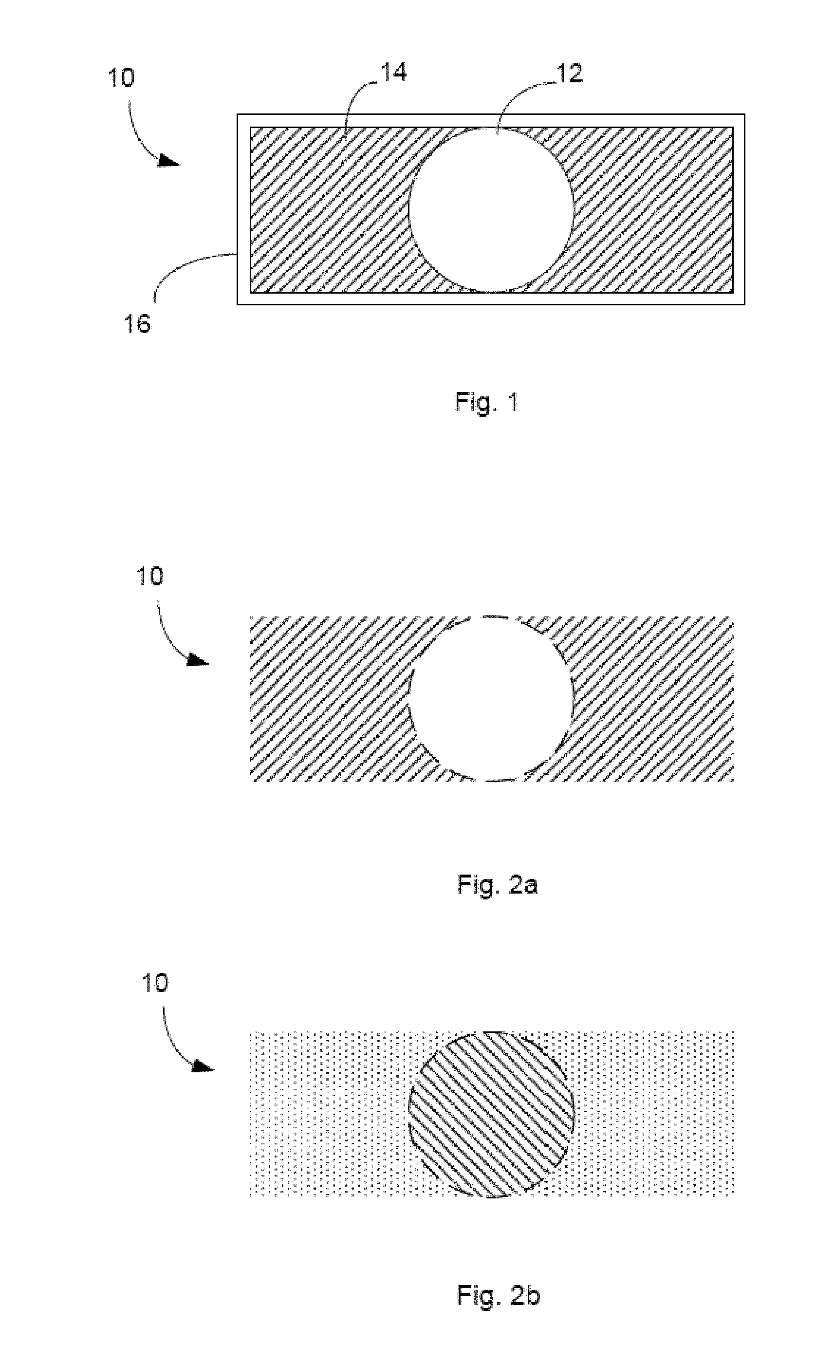
[0020]FIG. 1 shows a cross section of a marker 10 according to embodiments of the present invention. As will be explained below, the marker 10 is suitable for use in a variety of medical imaging systems using different imaging modalities.

[0021]In order to understand how the marker works, it is instructive first to consider the different imaging mechanisms which may be employed in medical imaging.

[0022]Magnetic resonance (MR) imaging operates by placing the imaging object in a high strength magnetic field. Currently, the field strength density typically varies from system to system between 0.2 and 3 T. In this strong magnetic field, the magnetic moments of hydrogen protons in the object become aligned with the magnetic field. By applying an electromagnetic signal having a resonant frequency to the object, the spins of those protons can be made to flip. When the electromagnetic signal is switched off, the protons flip back and emit an electromagnetic signal which can be received in re...


PUM


Abstract

Embodiments of the present invention provide markers, phantoms, and associated methods of calibration which are suitable for use in both medical resonance imaging and radiographic imaging systems. A marker includes a first component having a first hydrogen proton density and a first mass density; and a second component having a second hydrogen proton density different than the first hydrogen proton density, and a second mass density different than the first mass density. The first and second components are non-magnetic.

Description

TECHNICAL FIELD[0001]The present invention relates to medical imaging, and particularly to markers, phantoms, and associated methods of calibrating an imaging system which may be integrated with a radiotherapy system.BACKGROUND[0002]Recent developments in the field of radiotherapy have focussed on integrating an imaging system with the therapeutic system. The goal is to provide real-time feedback on the location of an anatomical feature within the patient (e.g. a tumour) such that a therapeutic radiation beam can be more accurately controlled to target that feature.[0003]One suggested approach is to combine a linear accelerator-based therapeutic system with a magnetic resonance imaging (MRI) system within a single apparatus, known as an MRI-Linac. Such apparatus is described in a number of earlier applications by the present Applicant, including U.S. patent application Ser. No. 12 / 704,944 (publication no 2011 / 0201918) and PCT publication no 2011 / 127947. In the system described in ea...

Claims


Application Information

Patent Timeline
IPC IPC(8): A61B6/00A61N5/10
CPCA61B6/583A61B19/54A61N5/1075A61N2005/1076A61B2019/5454A61B2019/5495A61B2019/5466G01R33/58A61B2017/00707A61B2017/00725G01R33/4808A61B2090/3995A61B90/39A61B2090/3954A61B2090/3966A61B6/582G01R33/4812A61B6/584
Inventor SELL, MARTINMILLS, DAVIDBYRNE, JULIANALLEN, JOHNROBERTS, DAVID ANTHONY
Owner ELEKTA AB
Why Eureka
Try Eureka