Plasma Confinement Device

a technology of plasma confinement and confinement device, which is applied in the field of confinement of ionized gas (plasma) and devices for plasma confinement, can solve the problem that cusp reactors invariably permit plasma to occupy the null poin

Active Publication Date: 2016-02-04
PRATER DANIEL
View PDF2 Cites 3 Cited by
  • Summary
  • Abstract
  • Description
  • Claims
  • Application Information

AI Technical Summary

Benefits of technology

[0017]In one form, not less than the following is accomplished. Plasma is confined in cusped magnetic fields and centrifugally rotated by E×B drift. In accordance with this form the convex shape of the cusped field ensures plasma stability and confinement of plasma along magnetic field lines is ensured by charged particle reflection at the cusps by the magnetic mirror effect, this longitudinal confinement being aided by the repelling forces of adjacent plasma currents. Still in accordance with this form, charged particles diffusing outwardly are retained against an outwardly increasing magnetic pressure and inwardly charged particles are drawn to the plasma sheath by the centrifugal force of plasma centrifugal rotation and viscosity. Still further in accordance with this form, momentum is transferred to plasma along the Poynting vector in the same direction as plasma fluid flow.

Problems solved by technology

More importantly, however, prior art cusp reactors invariably permit plasma to occupy the null point.

Method used


Image

  • Plasma Confinement Device
  • Plasma Confinement Device
  • Plasma Confinement Device

Examples


Embodiment Construction

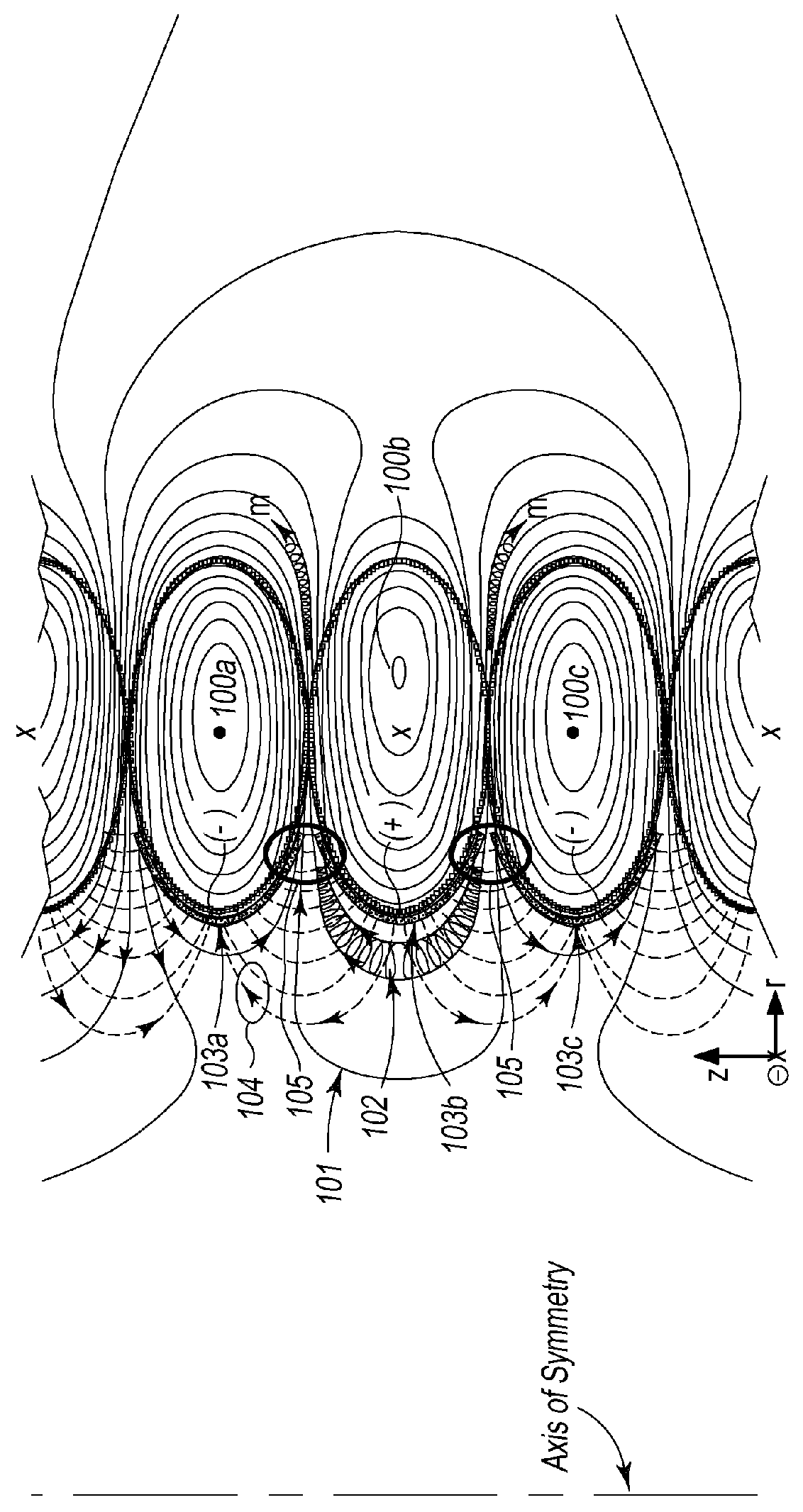
[0029]Referring now to FIG. 1, to create a cusped-geometry magnetic field for plasma confinement, magnetic confinement field coils 100 (“field coil”& etc.) of equal major radius are placed along a shared cylindrical axis in adequate proximity and energized such that adjacent magnetic fields oppose, exert a repelling Ampere force upon adjacent field coils 100, and generate cusps in the magnetic field in regions of space 105 (“the cusp”& etc.) for plasma 102 charged particle reflection or loss along magnetic field lines 101. In cylindrical coordinates the reactor may be of any length along the z-axis and of any radius and composed of any number of coils 100. In general the number of magnetic field coils 100 and electrodes 103 is N, the number of cusps 105 between magnetic fields therefore created is N−1, the number of confined plasmas 102 is N−2, and preferentially N is an odd number equal to or greater than 5. Plasma 102, illustrated to occupy the confinement region interior to magne...


PUM


Abstract

A device and method for the magnetic confinement of plasma is formed by a cylindrically stacked column of current-carrying magnetic field coils with electrodes interior to each magnetic field coil so as to induce plasma fluid rotation about an annular confinement region formed of cusped-geometry magnetic fields. Electrodes are formed such that the electric fields produced are tangential to the magnetic fields, and so as to maintain consistent azimuthal direction of plasma rotation, electric field electrodes alternate accordingly in polarity along the axial length of the device.

Description

CROSS-REFERENCE TO RELATED APPLICATIONS[0001]This non-provisional patent application is a continuation-in-part of U.S. Non-provisional patent application Ser. No. 14 / 505,864 filed Oct. 3, 2014 titled “Plasma Confinement Device” that claimed the benefit of and / or priority under 35 U.S.C. Section 119 to U.S. Provisional Patent Application Ser. No. 61 / 886,470 filed Oct. 3, 2013, titled “Plasma Containment Device”, U.S. Provisional Patent Application Ser. No. 61 / 986,263 filed Apr. 30, 2014, titled “Coaxial Mirror Confinement of Plasma”, and U.S. Provisional Patent Application Ser. No. 62 / 027,882, titled “Device For Plasma Containment”, the entire contents of each one of which is specifically incorporated herein by this reference.FIELD OF THE INVENTION[0002]The present invention relates in general to the subjects of ionized gas (plasma) confinement and devices for plasma confinement, and specifically, to devices and methods for plasma confinement in cusped magnetic fields with plasma rot...

Claims


Application Information

Patent Timeline
Patent Type & Authority Applications(United States)
IPC IPC(8): H05H1/11H05H1/03H05H1/16
CPCH05H1/11H05H1/03H05H1/16
Inventor PRATER, DANIEL
Owner PRATER DANIEL
Why Eureka
Try Eureka