
Vehicle-side connector

Active Publication Date: 2016-01-28
SUMITOMO WIRING SYST LTD
View PDF5 Cites 0 Cited by
  • Summary
  • Abstract
  • Description
  • Claims
  • Application Information

AI Technical Summary

Benefits of technology

The invention is a vehicle-side connector that allows for a relay circuit to be included between two vehicle-side terminals. This eliminates the need for a separate relay circuit that has to be constructed between wires, reducing labor and space requirements. Overall, the invention saves time and space in the design process.

Problems solved by technology

Further, since a mounting space for the vehicle-side connector is limited with the enlargement of the battery, space saving of the relay circuit has been desired.

Method used


Image

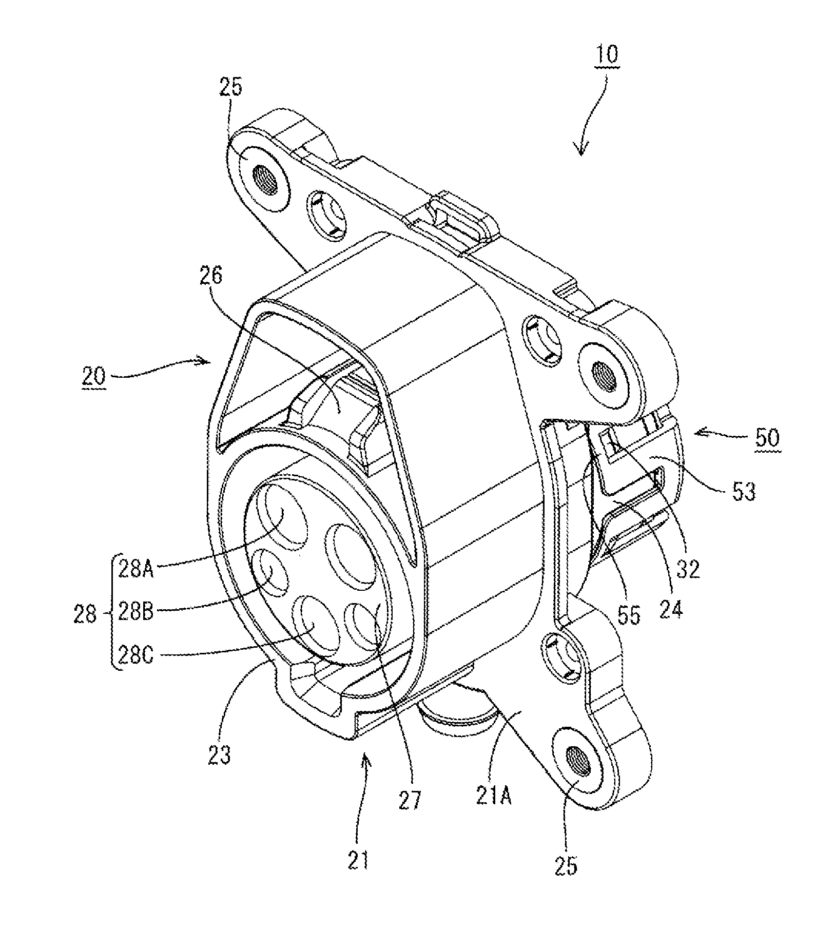
  • Vehicle-side connector
  • Vehicle-side connector
  • Vehicle-side connector

Examples


Embodiment Construction

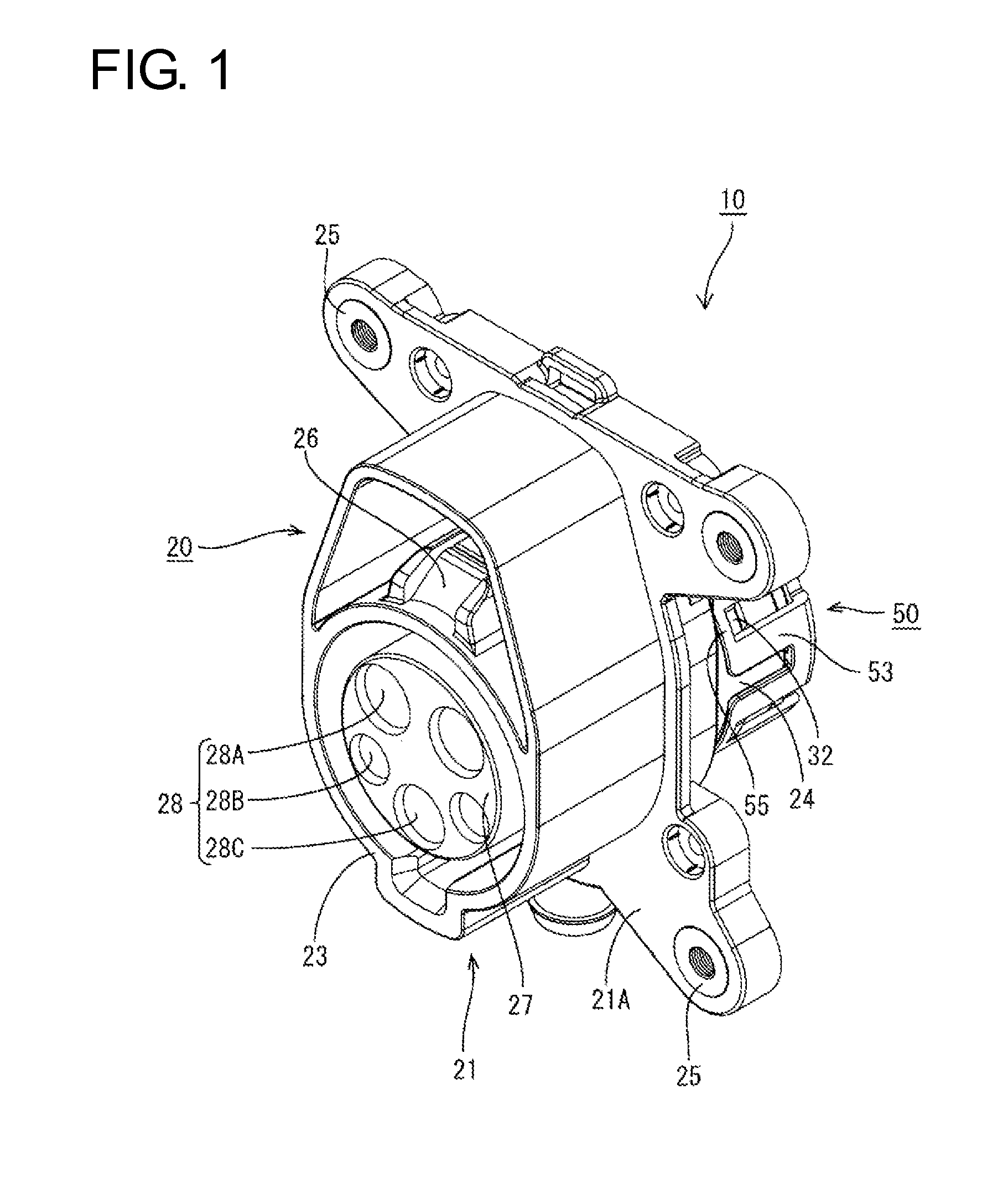
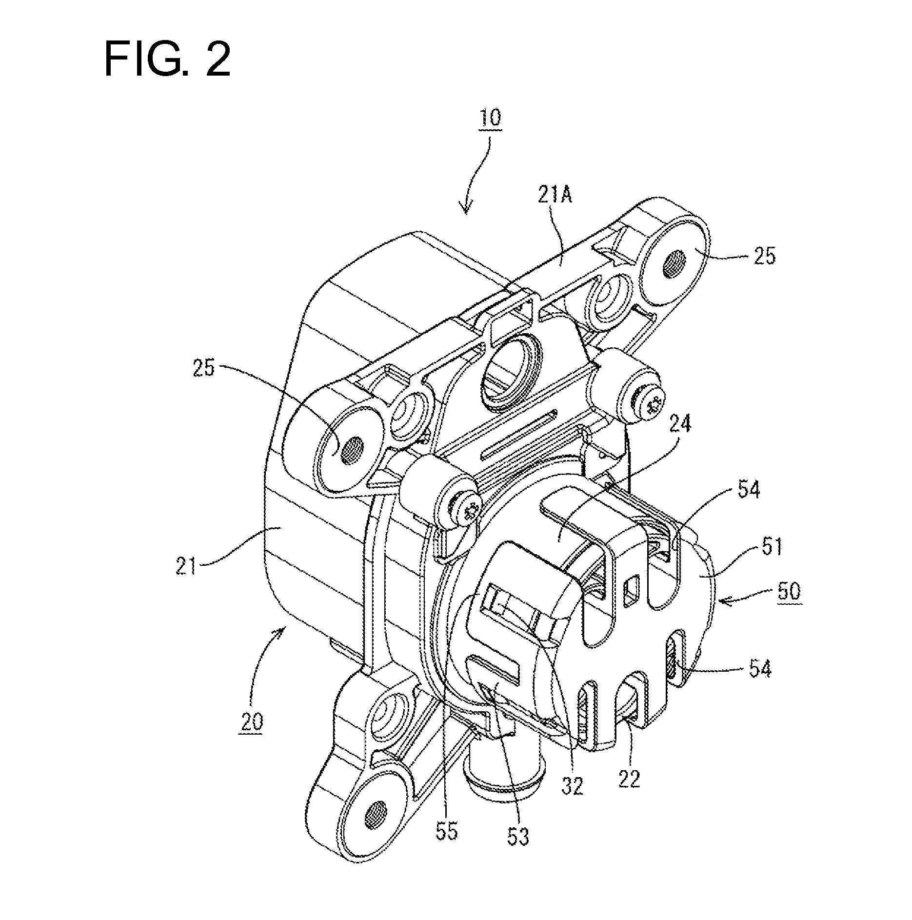
[0048]One embodiment of the present invention is described with reference to FIGS. 1 to 21.

[0049]This embodiment concerns a vehicle-side connector 10 to be connected to a battery (not shown) mounted in a vehicle, and the battery is charged by properly connecting a charging connector 80 connected to a power supply to this vehicle-side connector 10 and applying power.

[0050]Note that, in the following description, a vertical direction is based on a vertical direction in FIG. 3. Further, a front-back direction is based on a lateral direction in FIG. 4 and sides of the two connectors 10, 80 to be connected to each other are referred to as front sides on the basis of a connecting direction of the connectors 10, 80.

[0051]As shown in FIG. 21, the charging connector 80 is provided with a hollow cylindrical charging-side fitting portion 81 fittable into the vehicle-side connector 10. Terminal accommodating tube portions 84 in which charging terminals 83 are individually accommodated are forme...


PUM


Abstract

A vehicle-side connector (10) is connected to a battery mounted in a vehicle. The vehicle-side connector (10) includes a housing (20) configured such that a charging connector (80) is connected thereto. Vehicle-side terminals (40) individually are accommodated in cavities (28) in the housing (20) and are configured to be connected individually to charging terminals (83) in the charging connector (80) when the housing (20) and a charging-side fitting portion (81) in the charging connector (80) are connected. A resistance circuit unit (60) is accommodated in an accommodating portion (33) in the housing (20) and has a relay terminal (63) is arranged on a left side connected to a vehicle-side signal terminal (40B) and a relay terminal (63) is arranged on a right side connected to a vehicle-side ground terminal (40C).

Description

BACKGROUND[0001]1. Field of the Invention[0002]The present invention relates to a vehicle-side connector.[0003]2. Description of the Related Art[0004]A vehicle-side connector to be connected to an end of a wire extending from a battery mounted in a vehicle is known, for example, from Japanese Unexamined Patent Publication No. 2012-221612. A charging connector connected to a power supply is connectable to this vehicle-side connector and the battery is charged by properly connecting the vehicle-side connector and the charging connector.[0005]Further, a plurality of wires are drawn out from the vehicle-side connector and a relay circuit including a resistor is provided among these wires. When the vehicle-side connector and the charging connector are connected, the relay circuit is closed and a predetermined voltage value corresponding to the resistor is transmitted to a controller on a vehicle side, whereby a connected state of the vehicle-side connector and the charging connector is d...

Claims


Application Information

Patent Timeline
IPC IPC(8): H01R13/66H01R13/70
CPCH01R13/70H01R2201/26H01R13/6616
Inventor SHIMIZU, TOORU
Owner SUMITOMO WIRING SYST LTD
Learn More