Special seal geometry for exhaust gas sensors for producing high leak tightness with respect to the measurement chamber

a technology of exhaust gas sensors and sealing geometry, which is applied in the direction of branching pipes, machines/engines, instruments, etc., can solve the problems of loss of sealing rings, complex and difficult use of sealing rings, and only a poor sealing

Active Publication Date: 2016-01-28
ROBERT BOSCH GMBH
View PDF0 Cites 4 Cited by
  • Summary
  • Abstract
  • Description
  • Claims
  • Application Information

AI Technical Summary

Benefits of technology

This patent proposes a sensor system for measuring gas properties in a sealed space, which overcomes the limitations of existing systems. The system achieves a high sealing pressure through a linear seal, resulting in greater robustness against temperature and vibration fluctuations. Compared to existing flat seals, the system requires fewer components and reduces costs. The use of a flexible clamping between two linear seals improves sensor sensitivity and diagnostic capabilities, while ensuring excellent leak tightness. The use of a supported element as a cup spring improves probe vibration resistance.

Problems solved by technology

A planar seal of this kind as recited in the existing art, as discussed e.g. in DE 60 2005 002 375 T2 with a sealing ring between a probe and a measured-gas space and in DE 100 22 958 A1, is disadvantageous, however, since a planar seal has a large sealing area.
This makes possible only a poor sealing effect.
A seal of this kind having an additional sealing ring as recited in the existing art is additionally disadvantageous because installation of a probe, for example in an exhaust gas duct of an internal combustion engine, using a sealing ring can be complex and difficult, and it is moreover possible to lose the sealing ring during installation.
High costs for production, and high sensitivity to damage, can result therefrom.

Method used


Image

  • Special seal geometry for exhaust gas sensors for producing high leak tightness with respect to the measurement chamber
  • Special seal geometry for exhaust gas sensors for producing high leak tightness with respect to the measurement chamber
  • Special seal geometry for exhaust gas sensors for producing high leak tightness with respect to the measurement chamber

Examples


Embodiment Construction

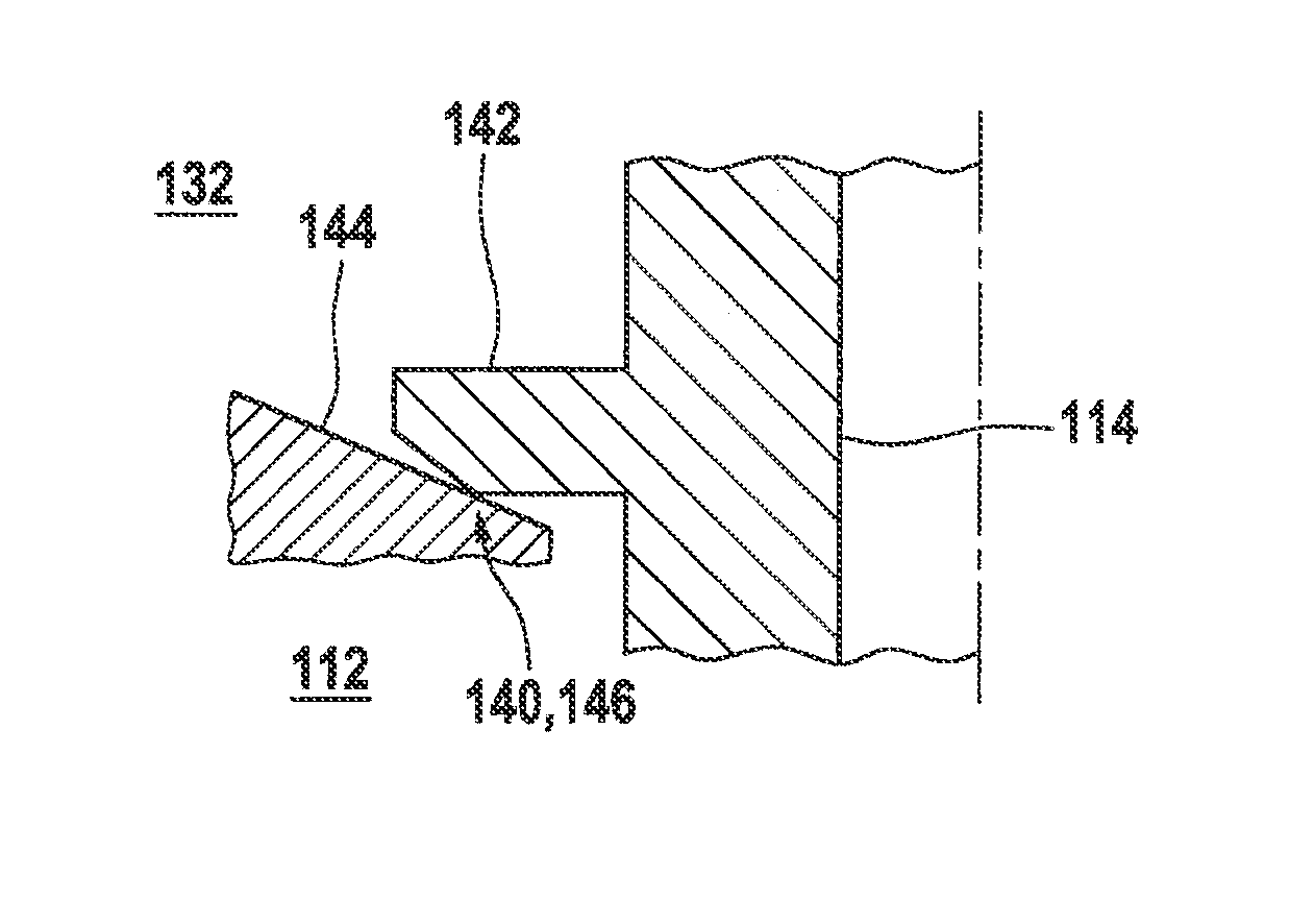
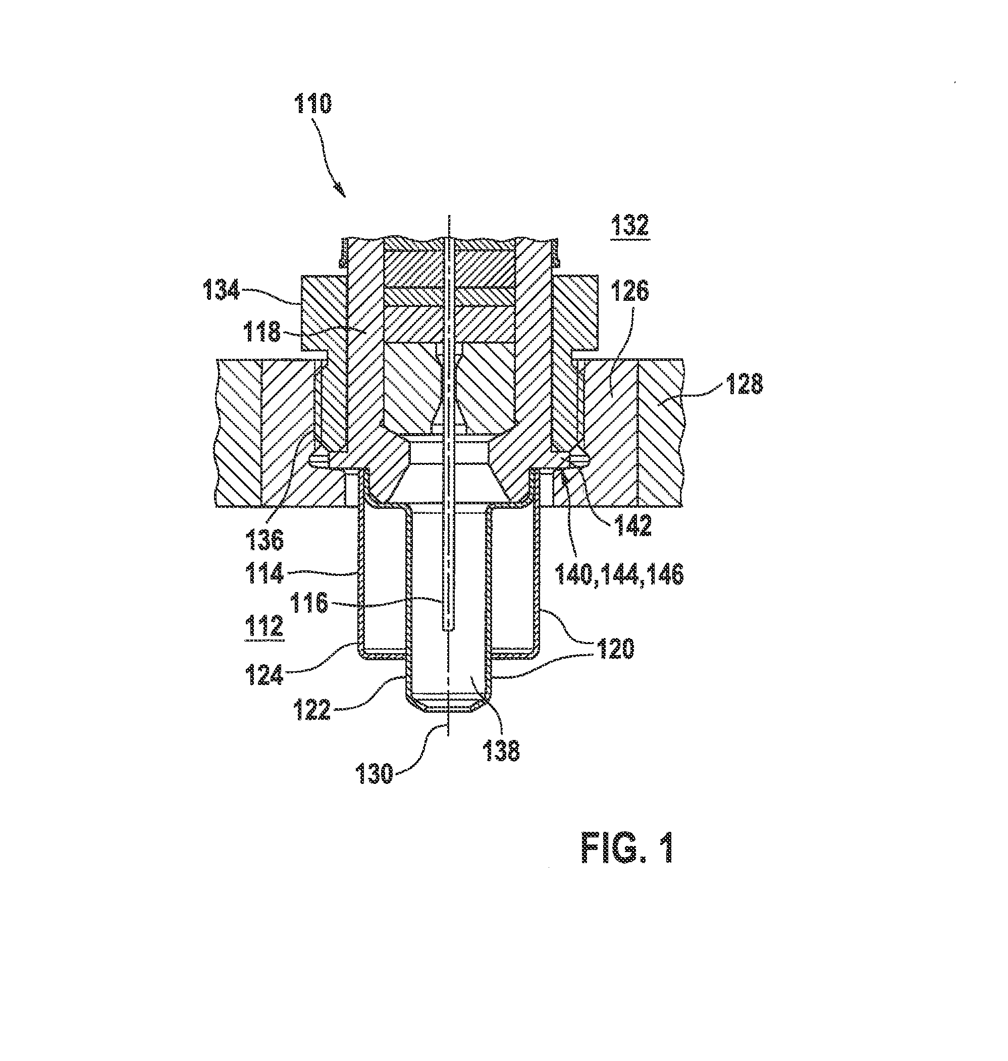
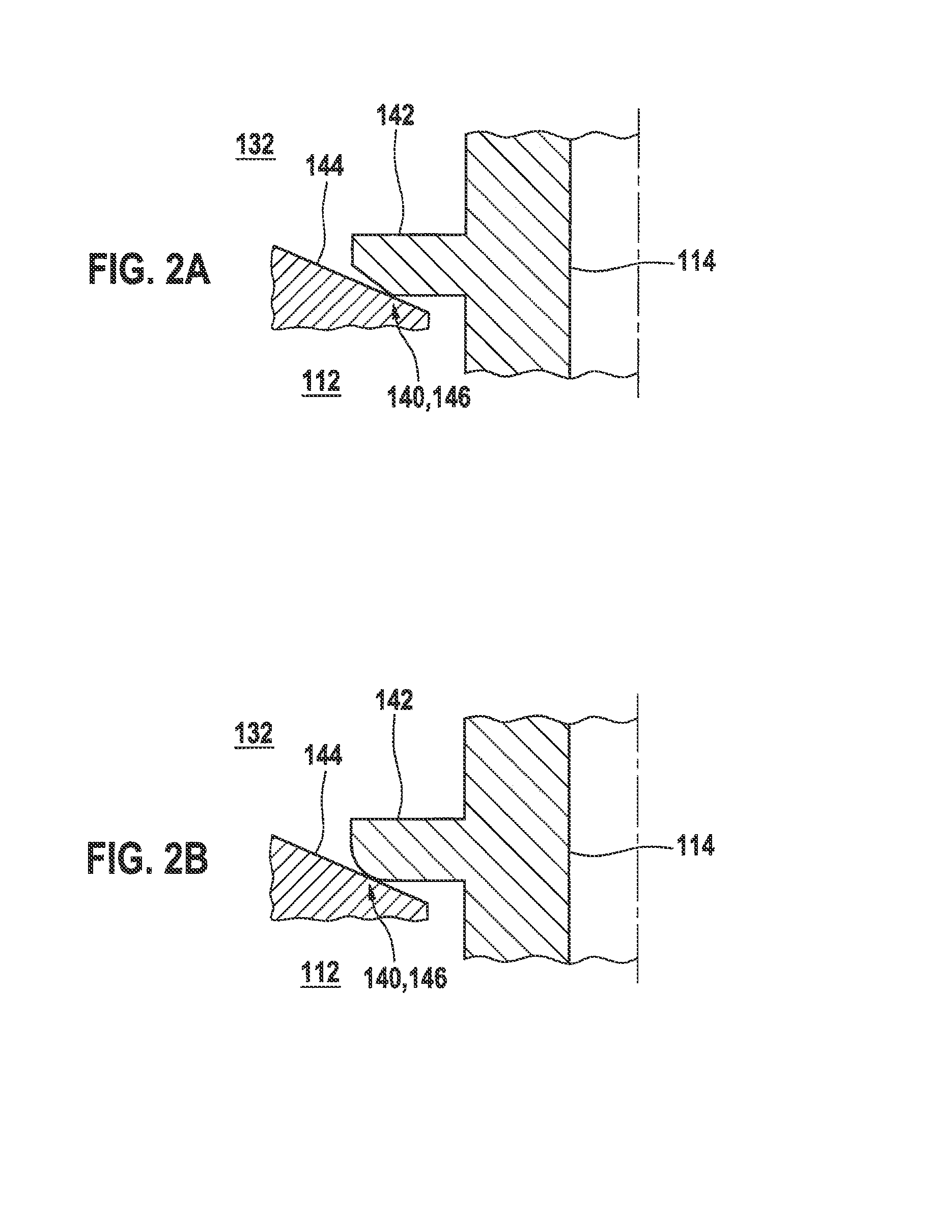
[0069]An exemplifying embodiment of a sensor system 110 according to the present invention for sensing at least one gas property of a measured gas in a measured-gas space 112 is depicted schematically in FIG. 1. Sensor system 110 has a probe 114 for sensing the property of the measured gas in measured-gas space 112. Probe 114 can be configured in particular as a lambda probe, which is used in particular to sense a gas component in an air / fuel mixture in an exhaust gas duct of a motor vehicle.

[0070]Measured-gas space 112 can accordingly be, in particular, a flow tube. Probe 114 can encompass a sensor element 116, configured for example as described in Konrad Reif (editor), “Sensoren im Kraftfahrzeug” [Sensors in motor vehicles], 2nd edition, 2012, pp. 160-165. Other embodiments of sensor element 116 are, however, possible in principle; for example, sensor element 116 can also be configured as a temperature sensor element or pressure sensor element or particle sensor element. Probe 11...


PUM


Abstract

A sensor system, for sensing at least one property of a measured gas in a measured-gas space, includes a probe for sensing the property of the measured gas. The probe has at least one sensor element and at least one housing surrounding the sensor element. The housing is configured so that the sensor element in the housing is capable of being impinged upon with the measured gas. The sensor system also includes a receiving element connectable to a wall of the measured-gas space. The probe is introducible along an insertion axis into the receiving element and securable in the receiving element. The probe is capable of being sealed off from the measured-gas space by at least one seal. The seal encompasses at least one linear seal.

Description

FIELD OF THE INVENTION[0001]The present invention relates to a special seal geometry for exhaust gas sensors for producing high leak tightness with respect to a measurement chamber.BACKGROUND INFORMATION[0002]A plurality of different sensor systems for sensing at least one property of a measured gas in a measured-gas space are believed to be understood. A “gas property” is to be understood in principle as any physical and / or chemical property of the measured gas, such that one or also several properties of the measured gas can be sensed. Qualitative and / or quantitative sensing of at least one property of a measured gas can be accomplished using such a sensor system, for example sensing of at least one gas component of the measured gas, in particular sensing of a gas component in an air / fuel mixture, and / or sensing of a particle concentration in the measured gas, in particular a particulate mass concentration. Alternatively or additionally, however, other properties of the measured g...

Claims


Application Information

Patent Timeline
IPC IPC(8): F01N13/00F16J15/06G01M15/10
CPCF16J15/062G01M15/104F01N13/008G01N27/407F16L9/18F16L41/008G01N15/06G01N27/4078
Inventor BUCHHOLZ, BASTIANDORAISAMY, NARENDIRANWILDE, JUERGENLINCK-LESCANNE, MARKUS
Owner ROBERT BOSCH GMBH
Why Eureka
Try Eureka