Systems and methods for transition-minimized data bus inversion

a data bus and transition-minimized technology, applied in the field of data bus inversion, to achieve the effect of improving power integrity and maximising power reduction

Active Publication Date: 2016-01-21
QUALCOMM INC
View PDF0 Cites 13 Cited by
  • Summary
  • Abstract
  • Description
  • Claims
  • Application Information

AI Technical Summary

Benefits of technology

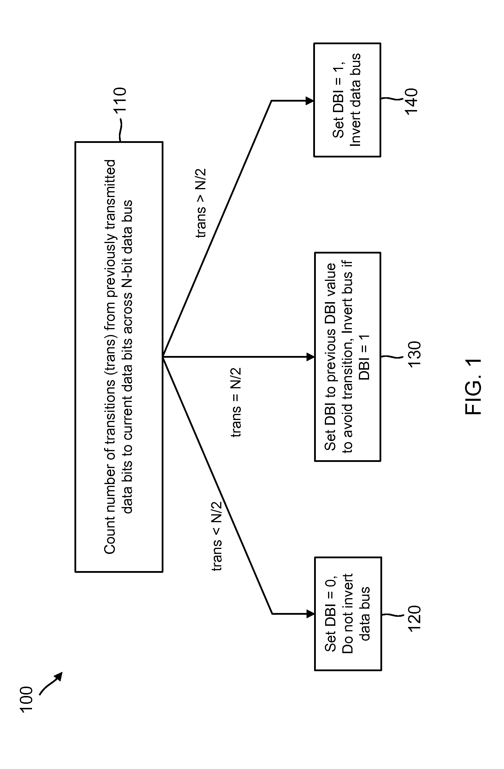
[0010]Various embodiments provide one or more advantages over conventional solutions. For instance, some embodiments improve upon the conventional DBI-AC scheme by additionally accounting for possible transitioning of the DBI bit. The result is the maximum number of transitions being no more than half of the data bus width. In an 8-bit data bus example, which is nine bits wide with the DBI bit, the maximum number of transitions with this improvement would be limited to four. This reflects a 20% maximum power reduction by virtue of limiting the maximum number of transitioning bits from five to four. Of course, the scope of embodiments is not limited to any particular number of bits in a bus. Such embodiments may further provide improved power integrity by reducing the current drawn from the supply or sent to ground

Problems solved by technology

Moreover, a large number of bit transitions may cause a phenomenon referred to as “ground bounce” or “supply bounce,” where the voltage supplied to a gate may temporarily dip and cause jitter.

Method used


Image

  • Systems and methods for transition-minimized data bus inversion
  • Systems and methods for transition-minimized data bus inversion
  • Systems and methods for transition-minimized data bus inversion

Examples


example circuit embodiments

[0047]FIG. 5 shows example inversion logic circuits 510 and 520 according to one embodiment. Inversion logic circuits 510 and 520 are shown with eight bits, through it is understood that the scope of embodiments may include inversion logic circuits adapted to employ any appropriate number of bits. For instance, in the embodiment of FIG. 6 (described below), inversion logic circuits 510 and 520 would employ thirty-two data bits as well as the DBI bit. Inversion circuit 510 may be included in a transmit path, whereas inversion circuit 520 may be included in a receive path.

[0048]Inversion logic circuit 510 includes on the left-hand side eight data bit inputs 0-7 and on the right-hand side eight data bit outputs 0-7 and a DBI bit output. Comparing logic 511 is employed to perform actions 110 and 410 (of FIGS. 1 and 4, respectively) to compare currently-received bits to previously-transmitted bits and identify a number of transitions. For instance, the bits may be received (as at action ...


PUM


Abstract

Circuits and methods for Data Bus Inversion (DBI) are provided. In one example, the immediately previous value of the DBI bit affects the next value of the DBI bit. Specifically, in some instances, the value of the DBI bit is held to the immediately previous value of the DBI bit to limit the total number of transitions on a data bus.

Description

TECHNICAL FIELD[0001]This application relates to Data Bus Inversion (DBI), and more particularly, to systems and methods to minimize data transitions using DBI.BACKGROUND[0002]In single-ended parallel Input / Outputs (IOs) such as a Double Data Rate (DDR) transfer-mode bus, data bus inversion (DBI) is an increasingly popular coding scheme that reduces signaling power and simultaneous switching output (SSO) noise, thereby improving power and signal integrity. An example is an 8-bit data bus. In an 8-bit DBI-encoded data bus, the eight data bits are transmitted either as-is or inverted for each bit unit interval. At each bit unit interval, an extra coding overhead bit (also referred to as the DBI bit) accompanies the transmitted data bits to inform the receiver whether an intentional bus-wide inversion took place. For example, when the coding overhead bit is set to a logical one, it may indicate that the data bits of the bus are inverted. The receiver receives the data bits and the over...

Claims


Application Information

Patent Timeline
Patent Type & Authority Applications(United States)
IPC IPC(8): G06F13/40G06F13/42
CPCG06F13/4208G06F13/4072
Inventor LOKE, ALVIN LENG SUNWEE, TIN TINBRYAN, THOMAS CLARK
Owner QUALCOMM INC
Why Eureka
Try Eureka