Carbon dioxide capture apparatus

a carbon dioxide and capture apparatus technology, applied in the field of carbon dioxide capture apparatuses, can solve the problems of increasing capture cost, rising sea level, and large amount of energy consumed to capture carbon dioxide from absorbents, so as to achieve the effect of reducing the amount of energy consumed to capture carbon dioxide, reducing the amount of energy supplied to or removed from absorbents, and saving energy consumption

Active Publication Date: 2016-01-21
KOREA RES INST OF CHEM TECH
View PDF4 Cites 5 Cited by
  • Summary
  • Abstract
  • Description
  • Claims
  • Application Information

AI Technical Summary

Benefits of technology

The carbon dioxide capture apparatus of the present invention has several technical benefits. It has a design that allows the absorbent to circulate through two columns where carbon dioxide is adsorbed and desorbed, respectively. This results in more efficient energy usage, saving energy across the process. Additionally, heat can be effectively exchanged between the absorbent after carbon dioxide adsorption and the absorbent after carbon dioxide desorption, resulting in reduced energy requirements. The heat exchange unit can be placed at different locations for improved heat exchange efficiency. Furthermore, the heat exchange unit is of a multi-tube or multi-plate type, which improves heat exchange efficiency between the absorbent after carbon dioxide adsorption and the absorbent after carbon dioxidation.

Problems solved by technology

Due to recent global warming, the polar icecaps have been melting, causing a rise in the sea level.
Attempts to suppress the emission of carbon dioxide by the introduction of carbon credits become economic issues in individual countries around the world.
According to such solid phase separation processes based on the concept of temperature swing adsorption, however, a vast amount of energy of at least 2 GJ / t-CO2 is consumed to desorb carbon dioxide from absorbents.
This energy consumption is a cause of increased capture cost, together with the cost of the absorbents.

Method used


Image

  • Carbon dioxide capture apparatus
  • Carbon dioxide capture apparatus
  • Carbon dioxide capture apparatus

Examples


Embodiment Construction

Problems to be Solved by the Invention

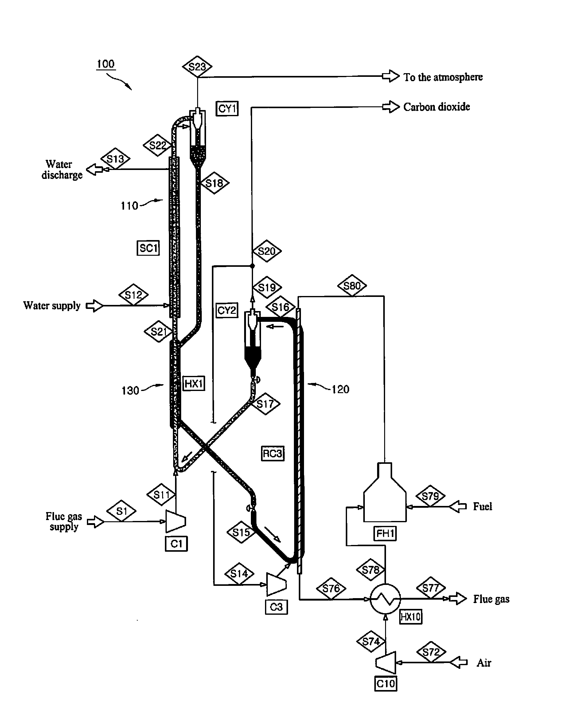
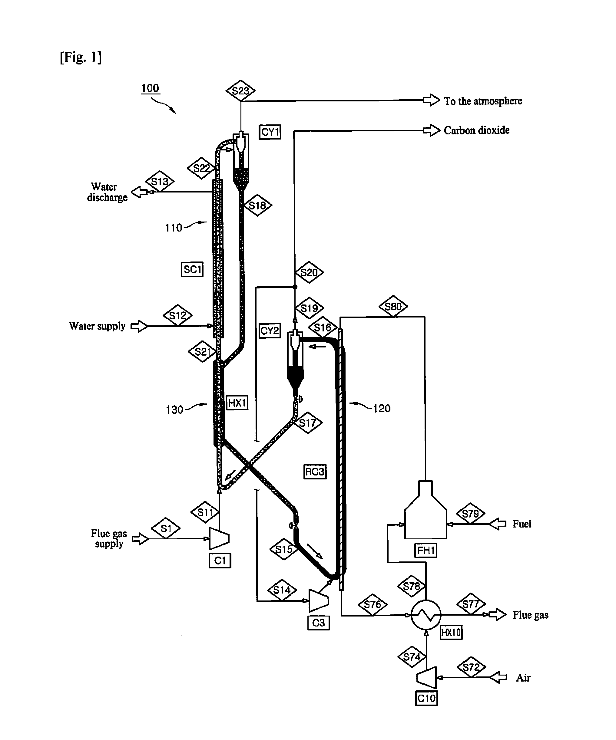
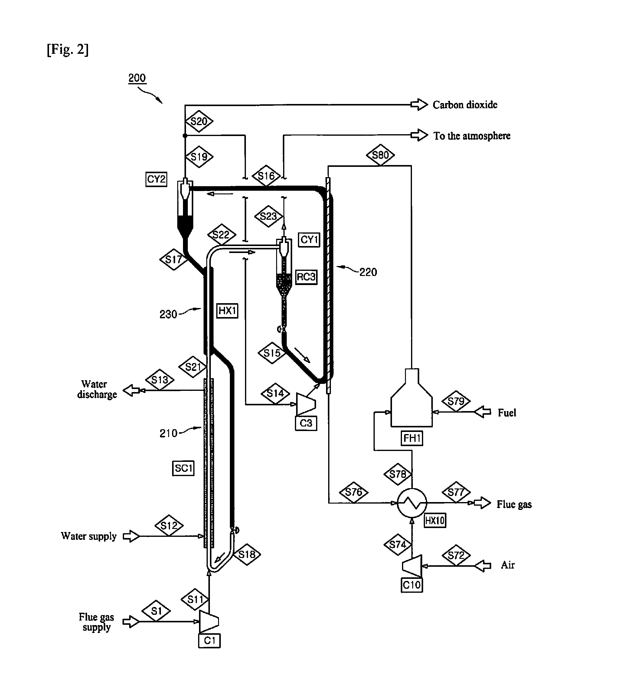
[0011]A first object of the present invention is to provide a carbon dioxide capture apparatus constructed such that heat is exchanged between an absorbent escaping from a carbon dioxide adsorption unit after carbon dioxide adsorption and the absorbent escaping from a carbon dioxide desorption unit after carbon dioxide desorption, contributing to the reduction of energy consumption needed to capture carbon dioxide.

[0012]A second object of the present invention is to provide a carbon dioxide capture method by which heat is exchanged between an absorbent escaping from a carbon dioxide adsorption unit after carbon dioxide adsorption and the absorbent escaping from a carbon dioxide desorption unit after carbon dioxide desorption, contributing to the reduction of energy consumption needed to capture carbon dioxide.

Means for Solving the Problems

[0013]In order to achieve the first object of the present invention, there is provided a carbon dioxide capt...


PUM

PropertyMeasurementUnit
temperatureaaaaaaaaaa
adsorptionaaaaaaaaaa
pressureaaaaaaaaaa

Abstract

The present invention relates to a carbon dioxide capture apparatus having a temperature swing adsorption mode for selective separation of carbon dioxide from flue gases. The carbon dioxide capture apparatus comprises: a carbon dioxide sorption column including a carbon dioxide adsorption unit in which adsorption of carbon dioxide from flue gases occurs; a carbon dioxide desorption column connected to the carbon dioxide sorption column and including a carbon dioxide desorption unit in which desorption of the adsorbed carbon dioxide occurs; a carbon dioxide absorbent repeatedly adsorbing and desorbing carbon dioxide while circulating through the carbon dioxide sorption column and the carbon dioxide desorption column; and a heat exchange unit in which heat exchange occurs between the absorbent after carbon dioxide adsorption and the absorbent after carbon dioxide desorption.

Description

TECHNICAL FIELD[0001]The present invention relates to a carbon dioxide capture apparatus, and more specifically to a carbon dioxide capture apparatus that prevents carbon dioxide present in flue gases from industrial facilities responsible for large emissions of carbon dioxide, such as power plants and steel mills, from being exhausted into the atmosphere.BACKGROUND ART[0002]Due to recent global warming, the polar icecaps have been melting, causing a rise in the sea level. Recent changes in climate have caused unusual weather phenomena around the world. Global warming is known to be attributed to increased greenhouse gas emissions. International agreements have been signed to restrict the emission of carbon dioxide. Attempts to suppress the emission of carbon dioxide by the introduction of carbon credits become economic issues in individual countries around the world. Efforts to reduce the emission of carbon dioxide have been directed towards the development of alternative energy so...

Claims


Application Information

Patent Timeline
Patent Type & Authority Applications(United States)
IPC IPC(8): B01D53/04C01B32/50
CPCB01D53/0462B01D2257/504B01D53/08B01D53/12B01D53/62B01D2251/30B01D2251/40B01D2253/102B01D2253/106B01D2253/108B01D2253/204B01D2258/025B01D2258/0283B01D2259/40098Y02C20/40B01D53/04B01D53/047B01J8/00
Inventor PARK, YONG KICHOI, WON CHOONKANG, NA YOUNGSEO, HWI MIN
Owner KOREA RES INST OF CHEM TECH
Why Eureka
Try Eureka