
Phase shifter and antenna device having same

a technology of phase shifter and antenna device, which is applied in the direction of antennas, waveguides, delay lines, etc., can solve the problems of unstable suppress the unintended variation in the amount of phase shift, and adjust the directivity of the antenna device.

Active Publication Date: 2016-01-14
HITACHI METALS LTD
View PDF3 Cites 10 Cited by
  • Summary
  • Abstract
  • Description
  • Claims
  • Application Information

AI Technical Summary

Benefits of technology

The present invention is a phase shifter that works with an antenna device. This phase shifter ensures that the signal has a consistent amount of phase shift. This improves the performance of the antenna system.

Problems solved by technology

In other words, the amount of phase shift is unstable.

Method used


Image

  • Phase shifter and antenna device having same
  • Phase shifter and antenna device having same
  • Phase shifter and antenna device having same

Examples


embodiment

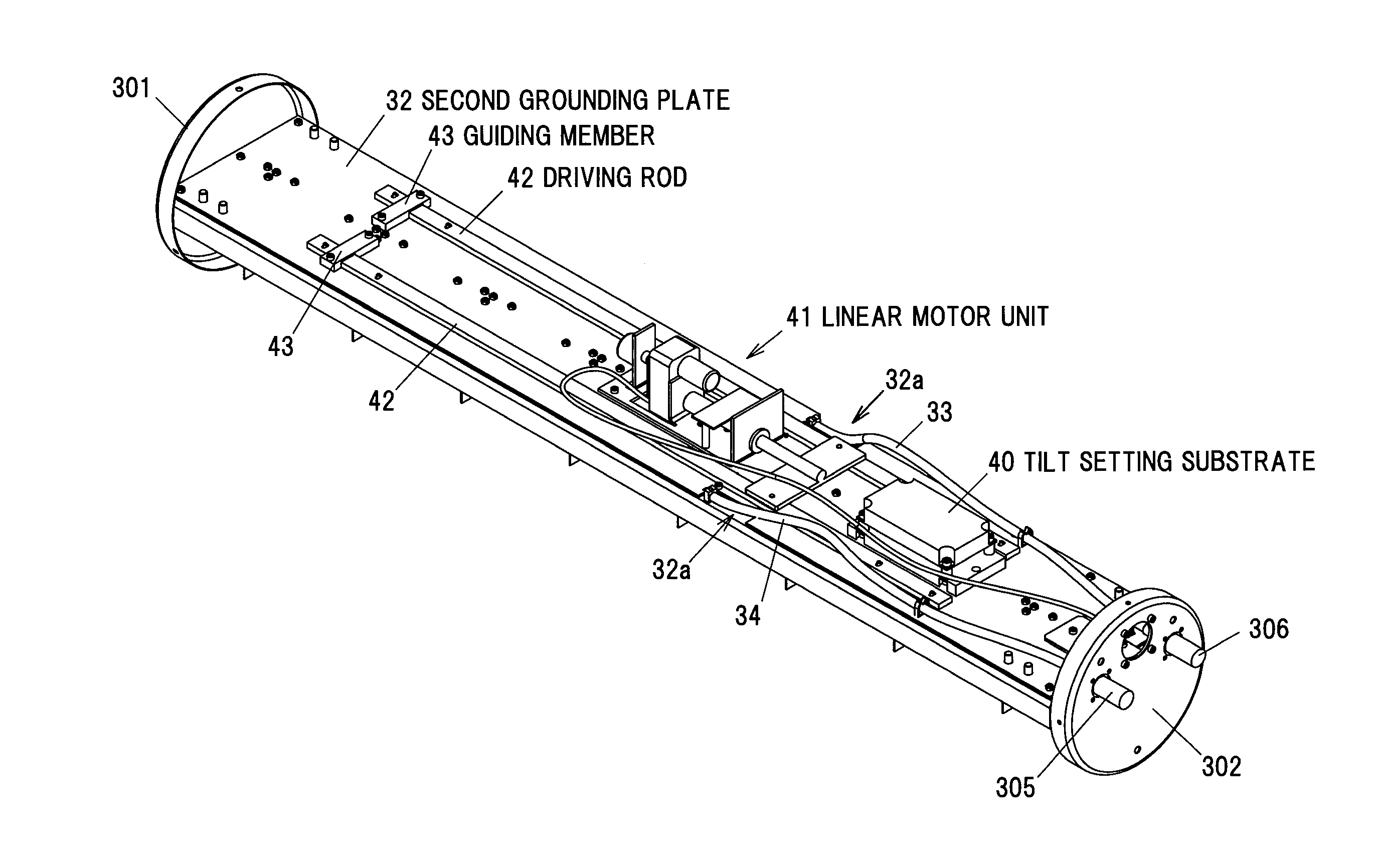
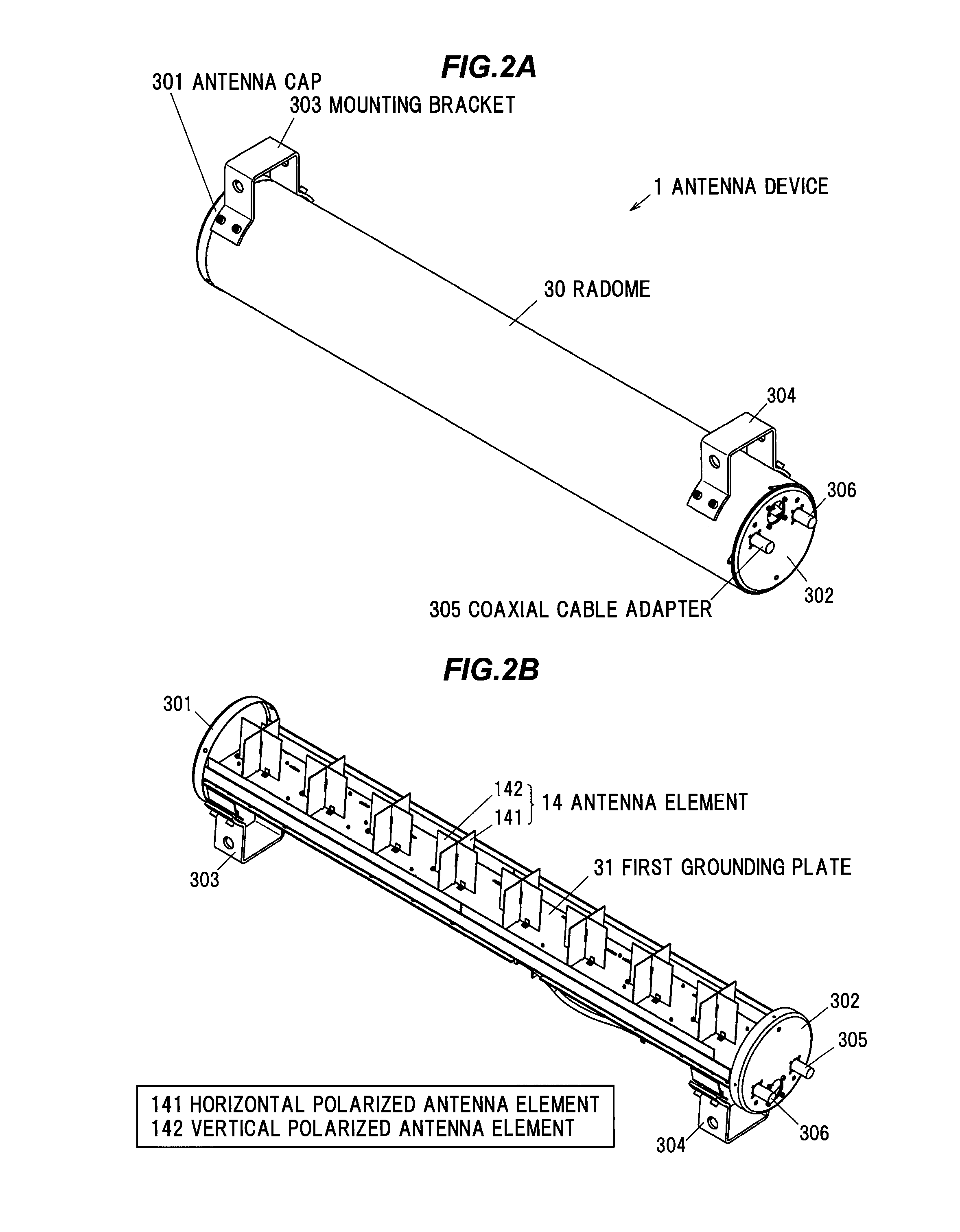
[0051]Below is described an embodiment for a phase shifter and an antenna device 1 according to the present invention, with reference to FIGS. 1 to 10. This antenna device 1 is used as a mobile phone base station antenna. It should be noted that in the following description the antenna device 1 in this embodiment is described as being used for high frequency signal transmission, but this antenna device 1 may be used for high frequency signal reception as well.

[0052](Function and Configuration of the Antenna Device)

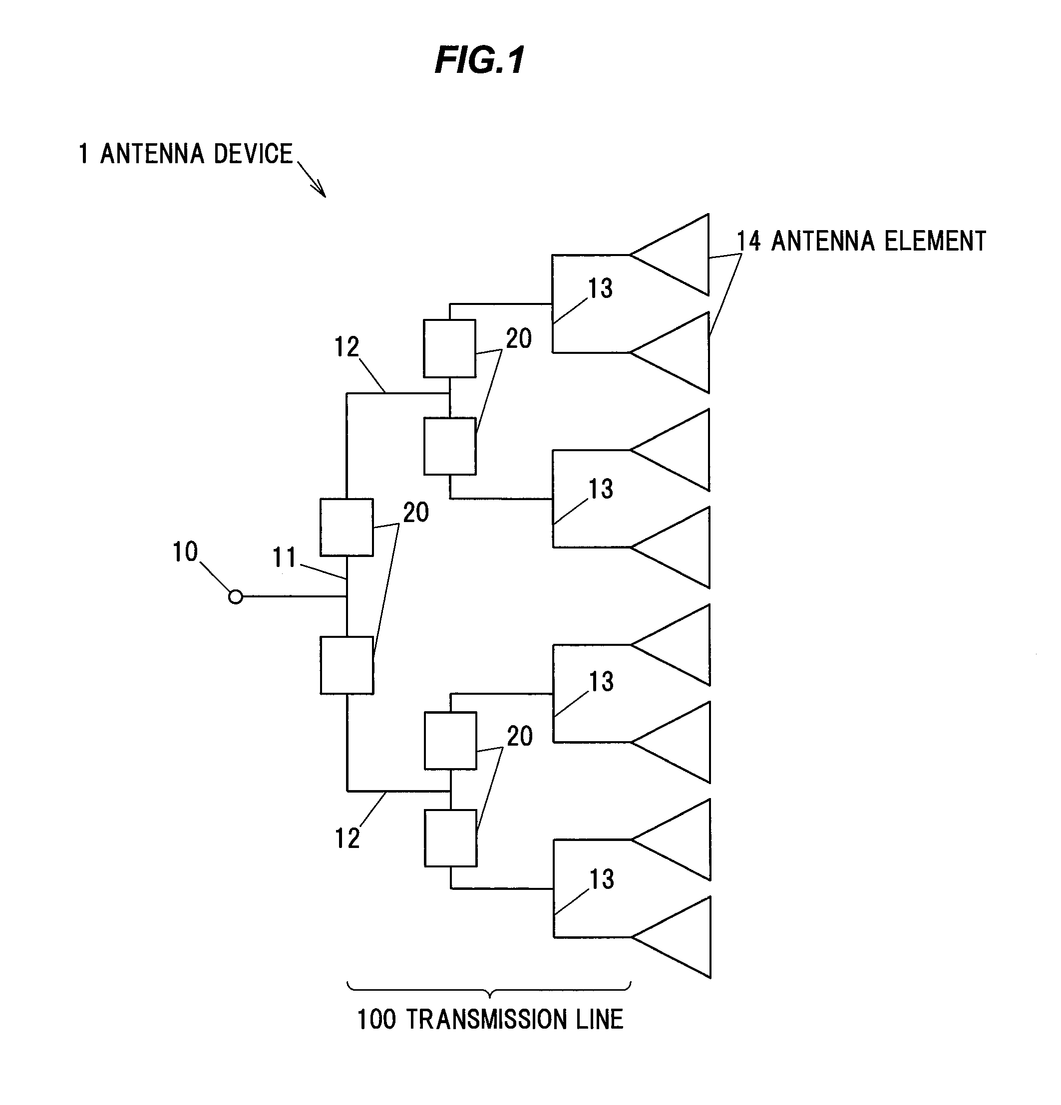
[0053]FIG. 1 is a schematic diagram showing a function and configuration of the antenna device 1 in the present embodiment. This antenna device 1 can transmit horizontal polarized and vertical polarized high frequency signals in a band of e.g. 1.5 to 2 GHz.

[0054]The antenna device 1 includes a plurality (in the present embodiment, eight) of antenna elements 14, and a transmission line 100 for transmitting a signal, which is input to an input 10 for a coaxial cable (not sho...


PUM


Abstract

A phase shifter includes dielectric members including facing portions facing a signal line formed on a surface of a substrate and being made of a dielectric material, a supporting member configured to support the dielectric members and receive a moving force for moving the dielectric members in a direction which is parallel to the substrate and crosses the signal line, and a moving mechanism configured to apply the moving force to the supporting member. At least either the dielectric members or the supporting member is provided with a protrusion configured to keep a distance between the facing portions of the dielectric members and the signal line.

Description

[0001]The present application is based on Japanese patent application No. 2014-144156 filed on Jul. 14, 2014, the entire contents of which are incorporated herein by reference.BACKGROUND OF THE INVENTION[0002]1. Field of the Invention[0003]This invention relates to a phase shifter, which is capable of changing a signal phase, and an antenna device equipped with that phase shifter.[0004]2. Description of the Related Art[0005]Conventionally, a phase shifter that is provided in a triplate line including a pair of outer conductors and an inner conductor arranged therebetween and is capable of changing a phase of a signal propagating in the inner conductor has been known (Refer to e.g. JP-A-11-340705).[0006]The phase shifter disclosed in JP-A-11-340705 includes a plate-shaped dielectric coupled to a driving rod to be moved forward or backward. The forward or backward movement of the driving rod results in the dielectric moving in a direction of crossing the inner conductor, and varying t...

Claims


Application Information

Patent Timeline
Patent Type & Authority Applications(United States)
IPC IPC(8): H01P1/18
CPCH01P1/181H01P1/184H01Q3/32
Inventor ISO, NAOKIISHIGAMI, YOSHIAKIKANETA, MASAHISAKITANO, NOBUAKIOGAWA, TOMOYUKIFUJISHIMA, TSUKASA
Owner HITACHI METALS LTD
Learn More