
Electric circuit-use core and device using the same

a technology of electric circuits and cores, applied in the direction of process and machine control, emergency power supply arrangements, magnetic bodies, etc., can solve the problems of inferiority of dust cores to ferrite in unique characteristics, and achieve the effects of wide operation range, low loss, and less susceptible to magnetic saturation

Inactive Publication Date: 2016-01-14
NTN CORP
View PDF0 Cites 10 Cited by
  • Summary
  • Abstract
  • Description
  • Claims
  • Application Information

AI Technical Summary

Benefits of technology

The present invention provides an electric circuit-use core that has low loss, is less susceptible to magnetic saturation, and allows for size reduction and current increase in high-frequency region. Additionally, the invention allows for efficient manufacturing of various electric circuit-use cores and provides high conversion efficiency in DC / DC and DC / AC conversion circuits.

Problems solved by technology

However, in a high-frequency region and in a high-current region, there is a problem of magnetic saturation which can be considered as the fate of ferrite.
With a core material called a dust core, it is possible to compensate for the above drawback of ferrite, but it is also well-known that the dust core is inferior to ferrite in unique characteristics such as iron loss.

Method used


Image

  • Electric circuit-use core and device using the same
  • Electric circuit-use core and device using the same
  • Electric circuit-use core and device using the same

Examples


Embodiment Construction

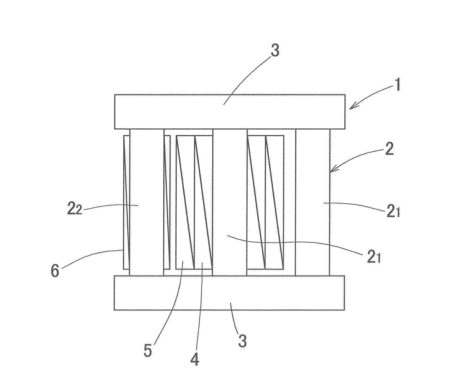
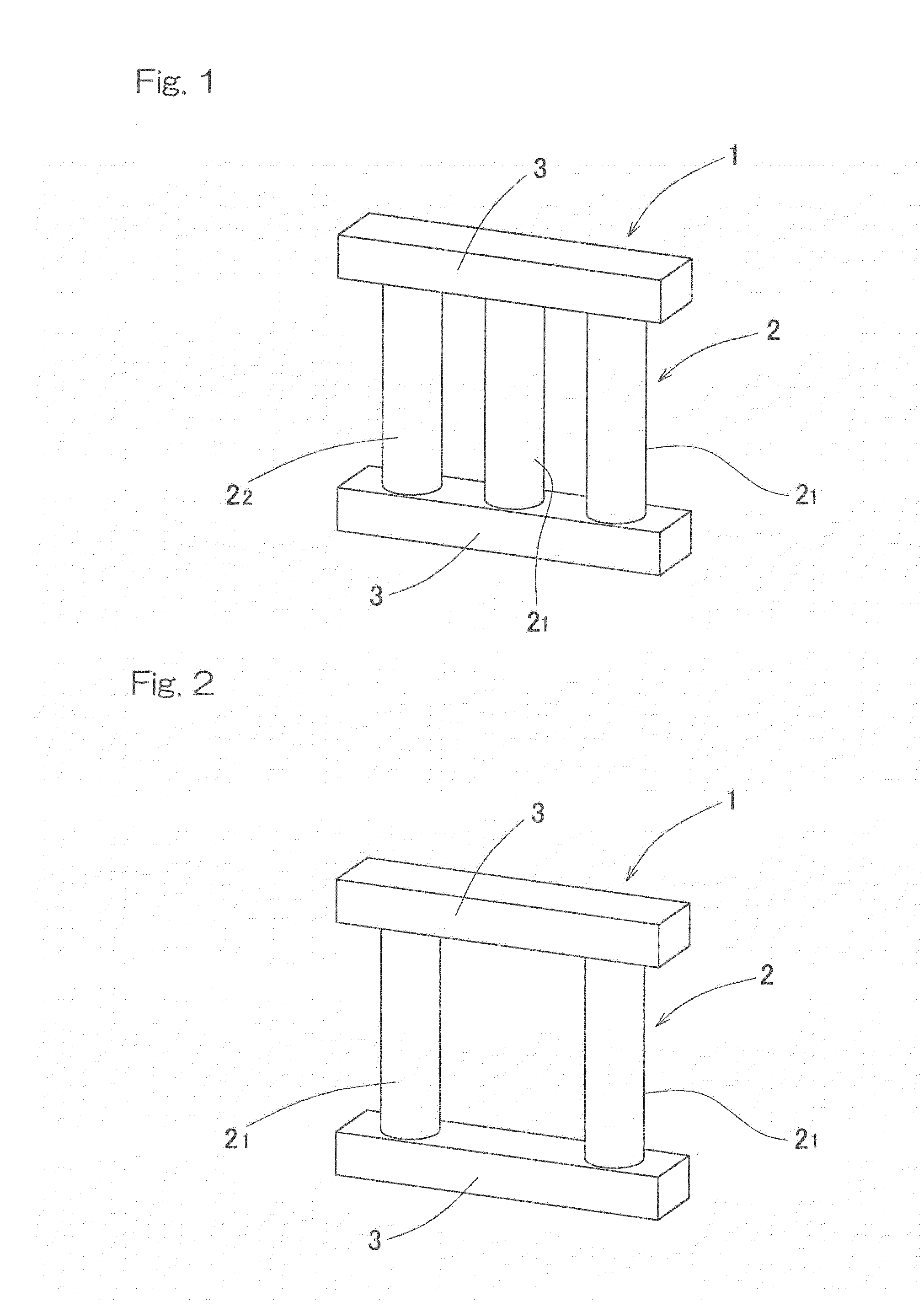
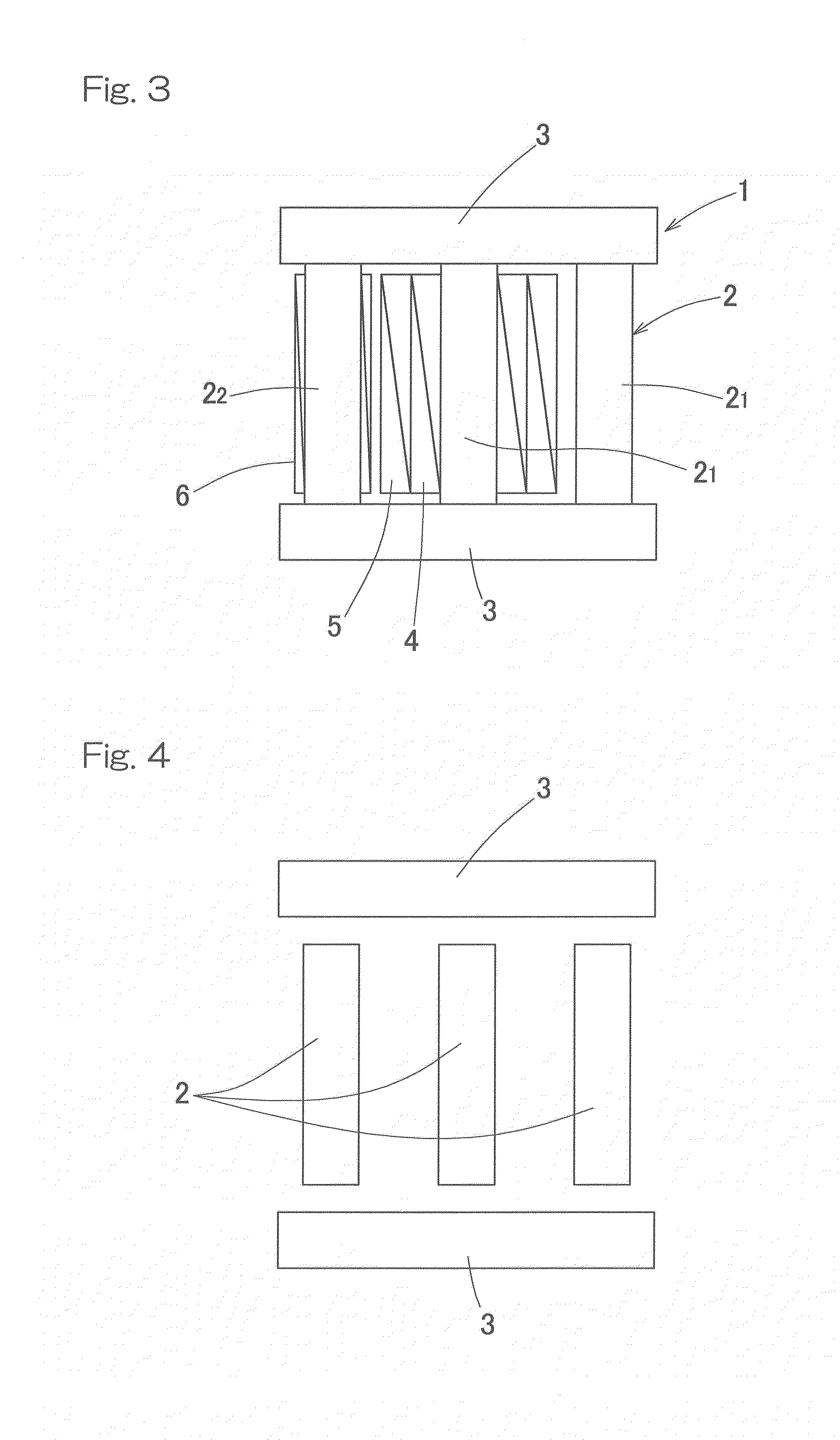
[0056]Embodiments of the present invention will be described with reference to the drawings. FIG. 1 is a perspective view showing an electric circuit-use core according to an embodiment of the present invention. The electric circuit-use core 1 is used as a transformer core, a choke core, or a core of a reactor, and includes a plurality of parallel pillar portions 2, each made of a magnetic material, and a plurality of connection portions 3 which connect one ends of these pillar portions 2 to each other and the other ends of these pillar portions 2 to each other, respectively. Each pillar portion 2 has a cylindrical shape in this example, and each connection portion 3 has a bar shape or a band-like plate shape with a rectangular cross section. In this present embodiment, there are provided three pillar portions 2 parallel to each other in a longitudinal direction. They include two main pillar portions 21, 21 which are disposed at the center of connection portion 3 and one end thereof...


PUM

PropertyMeasurementUnit
temperatureaaaaaaaaaa
crystallization onset temperatureaaaaaaaaaa
particle sizeaaaaaaaaaa

Abstract

An electric circuit-use core which has low loss, is less susceptible to magnetic saturation, thus allows for size reduction and current increase, and has a wide operation range in high-frequency region, and a manufacturing method for the core are provided. The electric circuit-use core is a dust core formed by compression molding or injection molding with an iron-based amorphous material, a cobalt-based amorphous material, or a sendust material as a magnetic material, and is used as a transformer core, a choke core, or a core of a reactor. The electric circuit-use core includes cylindrical pillar portions and connection portions.

Description

CROSS REFERENCE TO THE RELATED APPLICATION[0001]This application is a continuation application, under 35 U.S.C. §111(a), of international application No. PCT / JP2014 / 057156, filed Mar. 17, 2014, which is based on and claims Convention priority to Japanese patent application No. 2013-061529, filed Mar. 25, 2013, and Japanese patent application No. 2014-044972, filed Mar. 7, 2014, the entire disclosures of which are herein incorporated by reference as a part of this application.BACKGROUND OF THE INVENTION[0002]1. Field of the Invention[0003]The present invention relates to an electric circuit-use core such as a transformer core, a choke core, and a reactor-use core, and various devices using the electric circuit-use core, such as a solar cell power generation device, an on-vehicle step-up device, a charging station-use quick charging device, and an emergency power supply device for a data center.[0004]2. Description of Related Art[0005]Hitherto, as an electric circuit-use core, ferrite...

Claims


Application Information

Patent Timeline
Patent Type & Authority Applications(United States)
IPC IPC(8): H01F27/255B22F3/02B60L11/18C22C1/00C22C1/04C22C33/02C22C45/02C22C45/04H01F1/153H01F1/22H01F27/26H02J7/00H02J9/06H02M3/335H02M7/537
CPCH01F27/255C22C1/002H02J9/06H01F27/263H02M3/335H02M7/537B60L11/1803B22F3/02H01F1/153H01F1/15316H01F1/1535H01F1/22C22C45/02C22C45/04C22C1/0433C22C33/02H02J7/007H02M3/155H01F41/0246H01F1/15308B60L50/51Y02T10/70C22C1/11
Inventor NODA, HIROYUKIMORI, NATSUHIKOUEMOTO, LKUO
Owner NTN CORP
Learn More