
System and Method for Distributed Active Fluidic Bleed Control

a fluidic bleed and distributed technology, applied in water supply installation, air-flow influencers, transportation and packaging, etc., can solve the problems of insufficient control authority of conventional control surfaces, cumbersome design restrictions of moving bodies, limited use of passive porosity, etc., to reduce the adverse effects of flow-induced vibration, dampen the structural dynamics of the surface, and reduce the effect of passive porosity

Active Publication Date: 2016-01-14
GEORGIA TECH RES CORP
View PDF23 Cites 26 Cited by
  • Summary
  • Abstract
  • Description
  • Claims
  • Application Information

AI Technical Summary

Benefits of technology

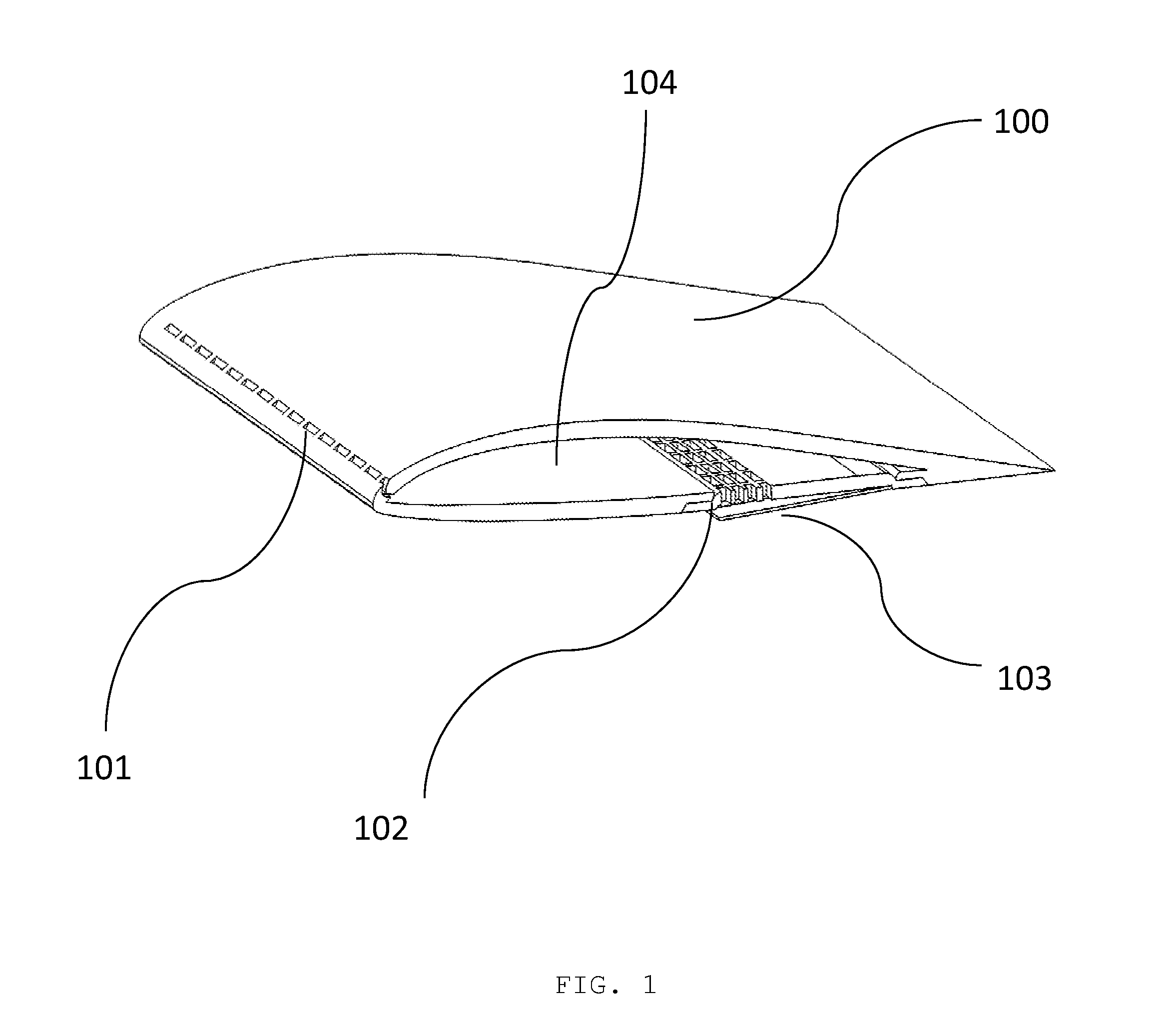
The present invention is about an active bleed regulation system that can change the stiffness, structure, and damping properties of a structure, such as a wing or other lifting surface, to mitigate or avoid adverse consequences of flow-induced vibrations and aeroelastic instabilities. It can also be used to tailor the aeroelastic behavior of the surface by varying the aerodynamic loads as a function of the elastic deflection to dampen structural dynamics of the surface.

Problems solved by technology

However, utilization of passive porosity is limited by factors such as inability to alter the control and to enable continuous regulation over a time-dependent movement of the moving surface.
The moving control surface does provide active control and regulation of the fluid flow, however, such control mechanisms are flawed with significant added weight and complexity which lead to cumbersome design restrictions of the moving body.
In addition, conventional control surfaces fail to generate sufficient control authority due to mechanical damage or design limits.
By way of example, flutter vibration can cause structural destabilization which can damage an aircraft in-flight.
Flutter is a self-starting and potentially destructive vibration where aerodynamic forces on an object coupled with a structure's natural mode of vibration produce rapid periodic motion.

Method used


Image

  • System and Method for Distributed Active Fluidic Bleed Control
  • System and Method for Distributed Active Fluidic Bleed Control
  • System and Method for Distributed Active Fluidic Bleed Control

Examples


Embodiment Construction

[0032]To facilitate an understanding of the principles and features of the various embodiments of the invention, various illustrative embodiments are explained below. Although exemplary embodiments of the invention are explained in detail, it is to be understood that other embodiments are contemplated. Accordingly, it is not intended that the invention is limited in its scope to the details of construction and arrangement of components set forth in the following description or illustrated in the drawings. The invention is capable of other embodiments and of being practiced or carried out in various ways. Also, in describing the exemplary embodiments, specific terminology will be resorted to for the sake of clarity.

[0033]It must also be noted that, as used in the specification and the appended claims, the singular forms “a,”“an” and “the” include plural references unless the context clearly dictates otherwise. For example, reference to a component is intended also to include composit...


PUM


Abstract

A system and method for regulating and actuating bleed over a structure exposed in a fluid motion are disclosed. The bleed inlet and outlet are formed on the surface of the structure establishing fluidic communication across surfaces. The disclosed system and method contemplates active control and regulation of the bleed to modify crossflow properties such as, aerodynamic forces, hydrodynamic forces, vorticity, and moments.

Description

CROSS-REFERENCE TO RELATED APPLICATIONS[0001]This application claims the benefit of U.S. Provisional Application No. 61 / 761,282 filed 6 Feb. 2013, the entire contents and substance of which is hereby incorporated by reference.STATEMENT REGARDING FEDERALLY SPONSORED RESEARCH OR DEVELOPMENT[0002]This invention was made with Government support under Agreement FA9550-08-1-0398, awarded by the Air Force. The Government has certain rights in the inventionBACKGROUND OF THE INVENTION[0003]1. Field of the Invention[0004]The present invention relates generally to fluid dynamics and bleed technology. More particularly, the present invention relates to system and method for active bleed regulation that can lead to control of global forces and structural stabilization.[0005]2. Description of Related Art[0006]Control of a moving body through a fluid has been traditionally achieved by employing a moving control surface to the moving body. The moving control surface, such as a flap or rudder, alter...

Claims


Application Information

Patent Timeline
Patent Type & Authority Applications(United States)
IPC IPC(8): B64C13/00G05D7/01
CPCG05D7/01B64C13/00B64C21/025B64C21/08B64C2230/06Y02T50/10
Inventor GLEZER, ARIKEARNEY, JOHN M.
Owner GEORGIA TECH RES CORP
Learn More