
Energy conversion system

a technology of energy conversion and energy storage, applied in the direction of machines/engines, wind turbines with solar radiation, chemical production, etc., can solve the problems of power generation capacity and consumption affecting, and achieve the effects of smarter, greener, and more distributed global energy, food and transportation infrastructur

Inactive Publication Date: 2016-01-07
ROBERTSON JOHN S
View PDF7 Cites 40 Cited by
  • Summary
  • Abstract
  • Description
  • Claims
  • Application Information

AI Technical Summary

Benefits of technology

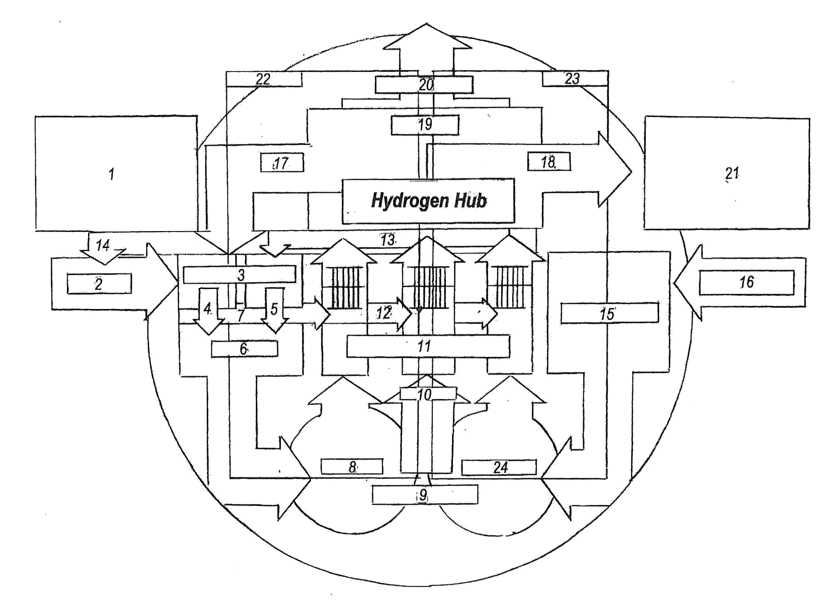
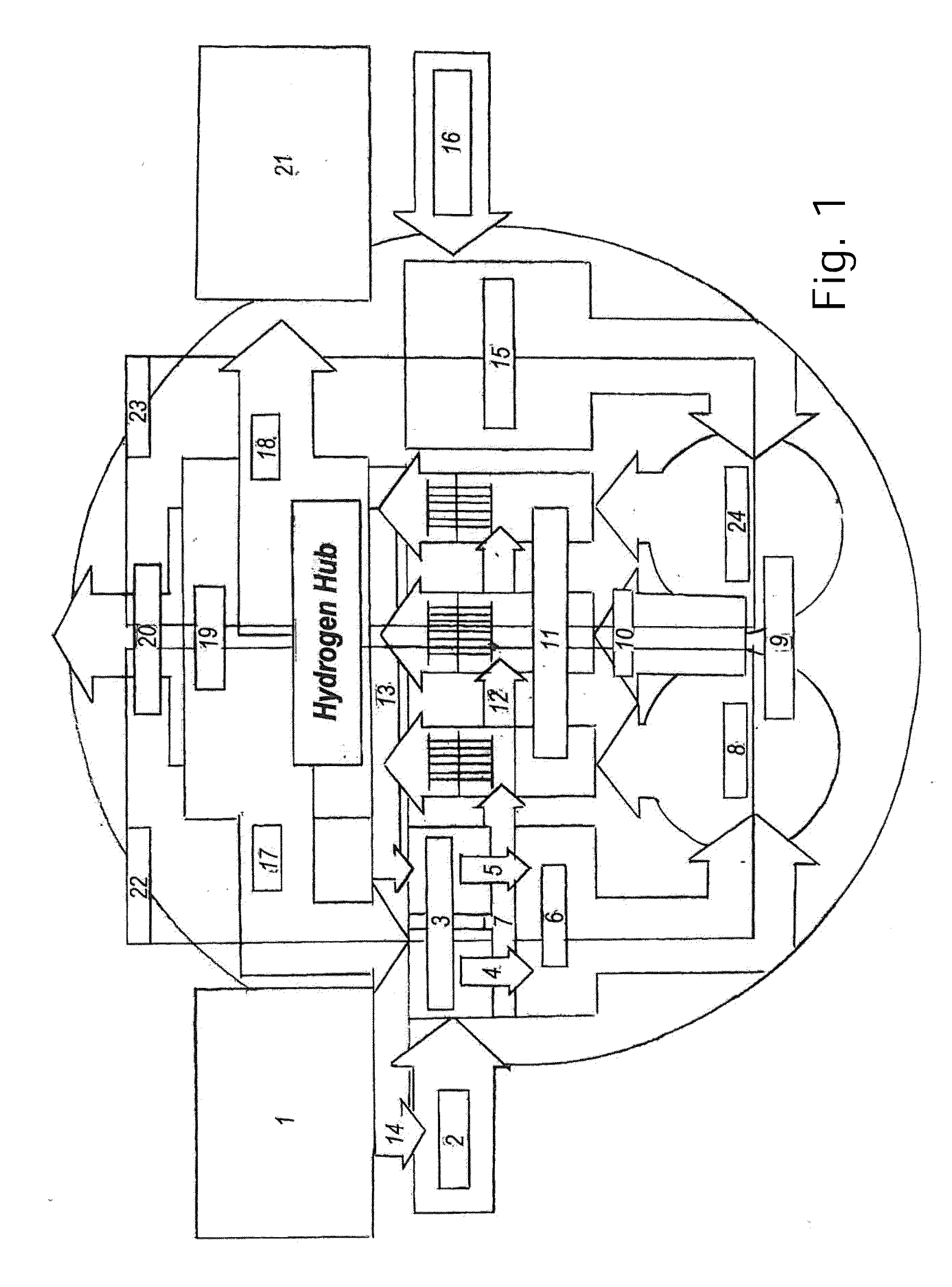
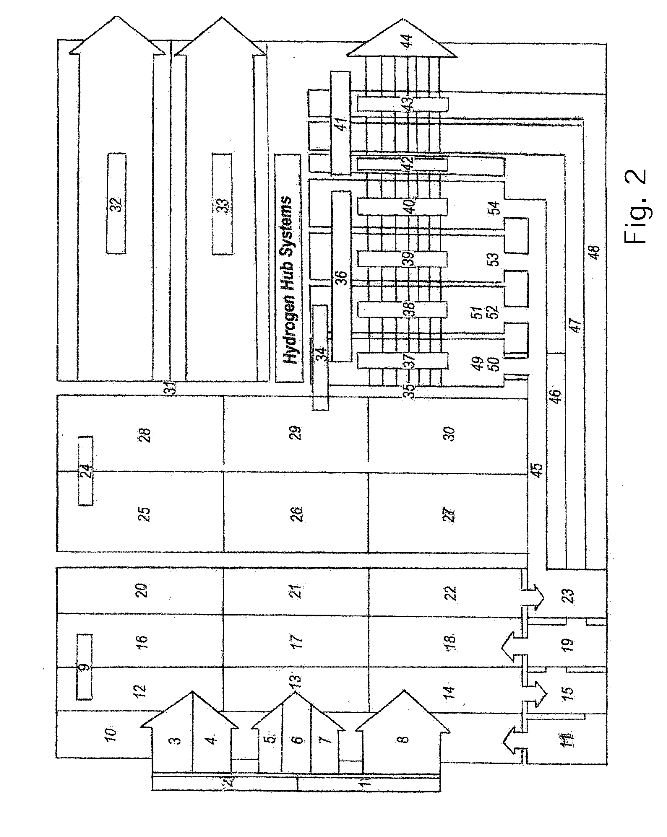
The Hydrogen Hub is a system designed to solve energy, food, and transportation challenges in the developed and developing world. It creates energy, fertilizer, and fuel by synthesizing electricity, water, and air into anhydrous ammonia and using it to create a smarter, greener, and more distributed global infrastructure. The hubs can be connected to the power grid and can be placed in strategic locations to capture off-peak resources, stabilize the power grid, and provide zero-emissions power generation. A global network of hydrogen hubs can help capture large-scale renewable and other energy resources, stabilize power grids, distribute on-peak, zero-pollution energy to load centers, create farm fertilizer, and create fuel to power cars and trucks with zero emissions.

Problems solved by technology

Finally, power generation capacity and consumption may be affected by less-obvious influences, such as a government's environmental policy, which may reward or punish energy production under certain circumstances (e.g. rewarding production with renewable energy sources or punishing production under unfavorable weather conditions or with nonrenewable energy sources).

Method used


Image

  • Energy conversion system
  • Energy conversion system
  • Energy conversion system

Examples


example

Improved System for Energy Shaping, Storage and Conversion Including Renewable Fuel Manufacturing from Recovered Power Generation Emissions

[0399]A self-fueled power generation, fuel storage and fuel recovery system is proposed, hereafter referred to as the “Hyper Loop.” The Hyper Loop is designed to be an exceptionally powerful, low cost, zero-pollution renewable energy storage and fuel recovery system.

[0400]The Hyper Loop continuously generates electric energy utilizing renewable fuel reconstituted from its own power plant emissions, integrating an ultra-efficient power generation plant with a closed-loop fuel recovery process. The Hydro Loop continuously manufactures, consumes and recaptures the most energy dense, zero-carbon fuel blend in the world. The fuel blend is composed of hydrogen, oxygen and nitrogen, among the most common elements on earth.

[0401]The Hydro Loop is an improved system of hardware and controls that: 1) utilizes certified renewable energy sources to extract h...


PUM

PropertyMeasurementUnit
compression ratiosaaaaaaaaaa
Direct combustion efficiencyaaaaaaaaaa
transmitting energyaaaaaaaaaa

Abstract

An improved system of hardware and controls, known as a Hyper Hub, that absorbs electric power from any source, including hydropower, wind, solar, and other renewable energy resources, chemically stores the power in hydrogen-dense anhydrous ammonia, then reshapes the stored energy to the power grid with zero emissions by using anhydrous ammonia to fuel diesel-type, spark-ignited internal combustion, combustion turbine, fuel cell or other electric power generators, and for other purposes.

Description

CROSS-REFERENCE TO RELATED APPLICATIONS[0001]This is a continuation-in-part of Ser. No. 13 / 749,631 filed Jan. 24, 2013 which is a continuation-in-part of Ser. No. 13 / 210,182 filed Aug. 15, 2011 which is a continuation of Ser. No. 12 / 406,894 filed Mar. 18, 2009 which claims priority to provisional application Ser. No. 61 / 070,065, titled “Energy Storage and Conversion Systems,” filed on Mar. 18, 2008. This application also incorporates by reference PCT Application No. PCT / US21011 / 052203 filed Sep. 19, 2011. All of the above disclosures of which are incorporated herein by reference in their entireties.INTRODUCTION[0002]Energy supply and demand is typically cyclic being influenced by both market and natural forces. For example, energy supply from renewable energy sources may be decreased or increased depending on circumstances of weather or human intervention. Hydroelectric power generation may be decreased by both a naturally lower mountain snowpack and a manmade reduction in outflow t...

Claims


Application Information

Patent Timeline
Patent Type & Authority Applications(United States)
IPC IPC(8): H01M8/06C01C1/04F01N3/00F02C3/20
CPCH01M8/0656C01C1/04H01M2220/10F02C3/20H01M8/0606F01N3/00C01B3/025C01B3/08C01B13/0207C01B13/0248C01B21/04C01B2203/0233C01B2210/0048C01C1/003C01C1/0405C01C1/0488C25B1/00C25B1/04C25B15/08F02C3/00F05B2220/61F05B2220/62F23C2900/9901F03D9/19H01M8/222Y02E10/72Y02E60/36Y02E60/50Y02E70/30Y02P20/133Y02P20/50Y02P20/52Y02A20/141F03D9/007F03D9/008
Inventor ROBERTSON, JOHN, S.
Owner ROBERTSON JOHN S
Learn More