
Display panel

a display panel and display panel technology, applied in the field of display panels, can solve the problems of unfavorable long life of passive matrix display apparatus, unfavorable large-scale products, and undesired mura or flicker of display panel b>2/b>, and achieve the effect of avoiding flicker of display panel with non-rectangular display area and different widths

Active Publication Date: 2016-01-07
INNOLUX CORP
View PDF5 Cites 3 Cited by
  • Summary
  • Abstract
  • Description
  • Claims
  • Application Information

AI Technical Summary

Benefits of technology

This solution effectively addresses the mura and flicker issues in non-rectangular display areas by controlling feed-through voltages, ensuring consistent image brightness and quality across the panel.

Problems solved by technology

Limited to the driving method, the passive matrix display apparatus is unfavorable for a long lifespan and large-scale products.
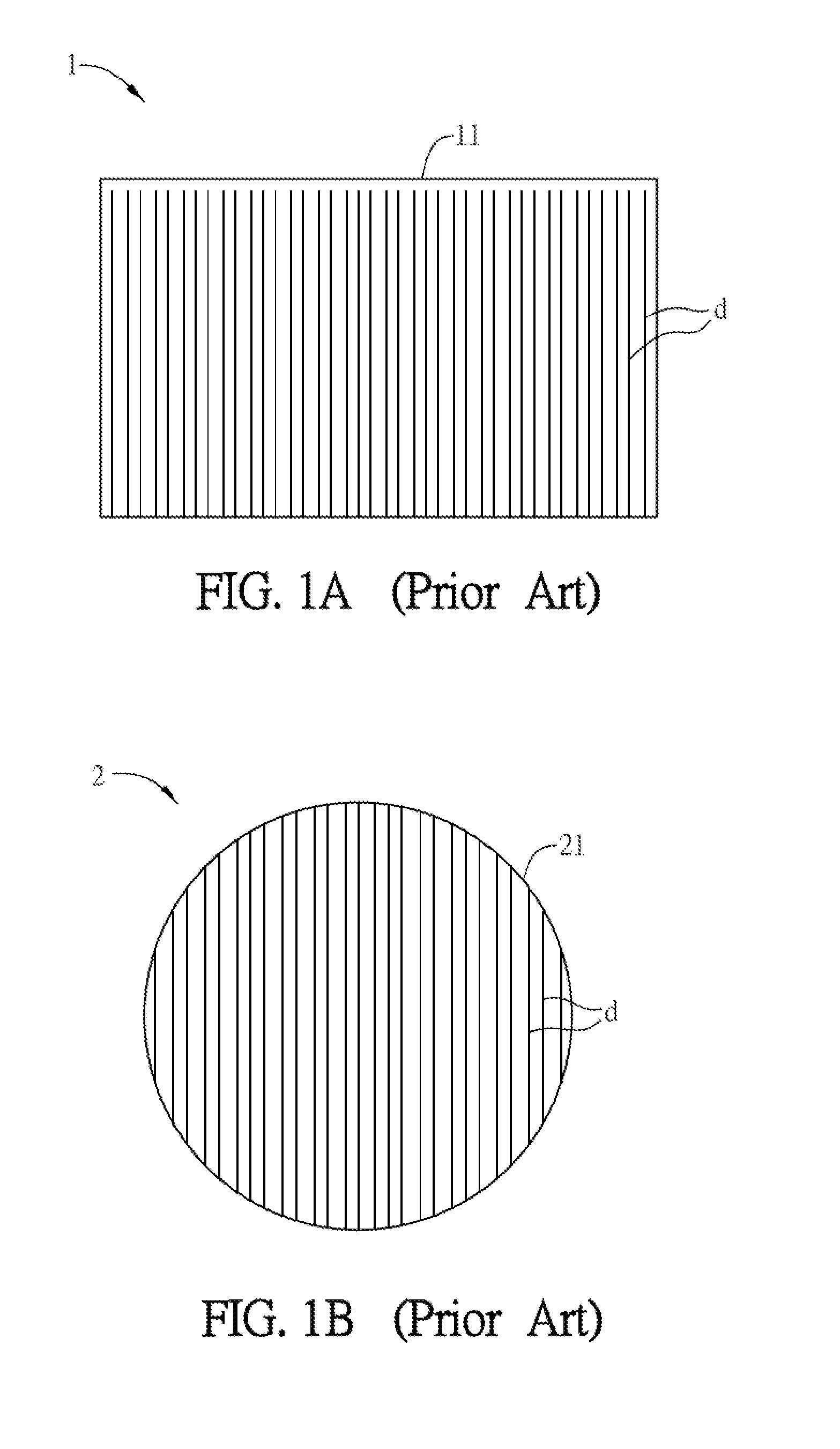
Accordingly, the variation of the feed-through voltages of the data lines d will result in the level shift of the common voltage (Vcom), and therefore the display panel 2 may have the undesired mura or flicker issue due to the uneven brightness.

Method used


Image

  • Display panel
  • Display panel
  • Display panel

Examples


Embodiment Construction

[0043]The present invention will be apparent from the following detailed description, which proceeds with reference to the accompanying drawings, wherein the same references relate to the same elements.

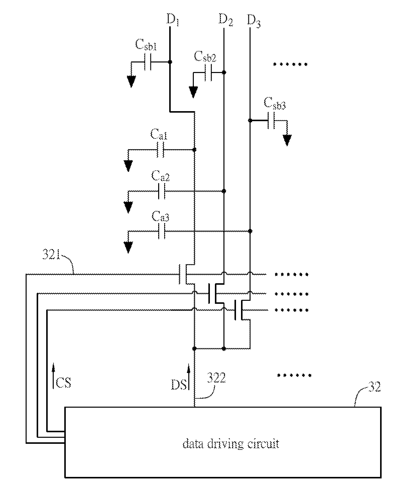
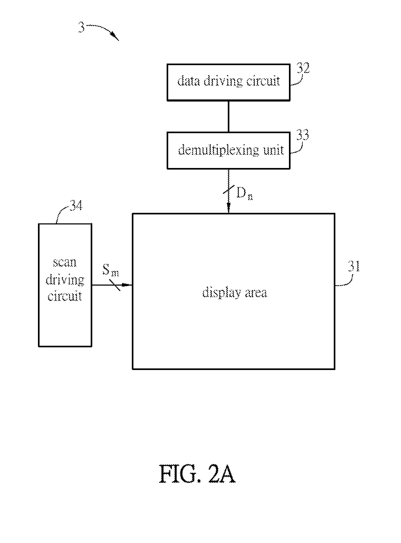
[0044]FIG. 2A is a schematic block diagram of a display panel 3 according to an embodiment of the invention, and FIG. 2B is a schematic diagram showing the relation between a display area 31 and a demultiplexing unit 33 of the display panel 3 in FIG. 2A. The display panel 3 is an active matrix display panel and can be a liquid crystal display (LCD) panel, an organic light-emitting diode (OLED) display panel, an organic electroluminescence (EL) display panel or other kinds of display panels for example. To be noted, FIG. 2B just shows the relation between the display area 31 and the demultiplexing unit 33 while other elements of the display panel 3 are omitted.

[0045]The display panel 3 includes a plurality of scan lines Sm, a plurality of data lines Dn, a data driving circuit 32 and a ...


PUM


Abstract

A display panel comprises a display area, a plurality of scan lines and data lines, a data driving circuit and a demultiplexing unit. The scan lines and the data lines cross each other within the display area. At least two of the data lines have different capacitances. The data driving circuit outputs a plurality of control signal and a data signal. The demultiplexing unit includes a plurality of thin-film transistors coupled with the data driving circuit and the data lines. The thin-film transistors receive the data signal and transmit the data signal to the correspondingly coupled data lines through channel layers of the thin-film transistors according to the control signals. The channel layers of at least two of the thin-film transistors coupled with the at least two data lines have different widths.

Description

CROSS REFERENCE TO RELATED APPLICATIONS[0001]This application is a Continuation application of U.S. application Ser. No. 14 / 197,763 filed on Mar. 5, 2014.BACKGROUND OF THE INVENTION[0002]1. Field of Invention[0003]The invention relates to a display panel and, in particular, to a display panel having a non-rectangular display area.[0004]2. Related Art[0005]Flat display apparatuses have advantages such as low power consumption, less heat generation, light weight and non-radiation, and are therefore widely applied to various electronic products. A flat display apparatus can be divided into a passive matrix type and an active matrix type according to its driving method. Limited to the driving method, the passive matrix display apparatus is unfavorable for a long lifespan and large-scale products. Although the active matrix display apparatus is made by the advanced technology, it is suitable for the large-scale and high-definition full color display with a large information capacity and ...

Claims


Application Information

Patent Timeline
Patent Type & Authority Applications(United States)
IPC IPC(8): G09G3/36
CPCG09G3/3648G09G2300/0404G09G2320/0233G09G2310/0297G09G2320/0247G09G2300/0426G09G3/3685G09G2320/0219G09G2300/0478
Inventor WATSUDA, HIROFUMIHAGINO, SHUJI
Owner INNOLUX CORP
Learn More