
Optical detection apparatus and methods

a technology of optical detection and optical proximity sensor, applied in the field of computerized apparatus and methods, can solve problems such as unreliability of existing infrared optical proximity sensing methods, unreliability of ultrasonic proximity sensors, and various disabilities

Inactive Publication Date: 2016-01-07
BRAIN CORP
View PDF8 Cites 52 Cited by
  • Summary
  • Abstract
  • Description
  • Claims
  • Application Information

AI Technical Summary

Benefits of technology

The present patent is about an improved object detection apparatus and methods. The technical effects of the patent include the ability to detect the distance to an object using a high-pass filtered version of an image, based on a deviation parameter between the image and a reference value. The apparatus includes a lens, image sensor, and logic to evaluate the image and produce an object detection indication based on the contrast parameter breaching a threshold. The method can be used in robotic navigation, where the apparatus detects the presence of an object and activates the actuator accordingly. The patent also describes a system for detecting targets or obstacles and selectively activating the actuator based on the determination.

Problems solved by technology

Small sized and / or low-cost robotic vehicles may comprise limited processing and / or energy resources (and / or weight budget) for object detection.
A variety of object detection apparatus (such as IR-based, ultrasonic, and lidar) currently exist, but suffer from various disabilities.
Specifically, some existing infrared (IR) optical proximity sensing methods may prove unreliable, particularly when used outdoors and / or in presence of other sources of infrared radiation.
Ultrasonic proximity sensors may become unreliable outdoors, particularly on e.g., unmanned aerial vehicles (UAV) comprising multiple motors that may produce acoustic noise.
Lidar based systems are typically costly, heavy, and may require substantial computing resources for processing lidar data.

Method used


Image

  • Optical detection apparatus and methods
  • Optical detection apparatus and methods
  • Optical detection apparatus and methods

Examples


Embodiment Construction

[0040]Implementations of the present disclosure will now be described in detail with reference to the drawings, which are provided as illustrative examples so as to enable those skilled in the art to practice the present technology. Notably, the figures and examples below are not meant to limit the scope of the present disclosure to a single implementation, but other implementations are possible by way of interchange of or combination with some or all of the described or illustrated elements. Wherever convenient, the same reference numbers will be used throughout the drawings to refer to same or like parts.

[0041]Although the system(s) and / or method(s) of this disclosure have been described in detail for the purpose of illustration based on what is currently considered to be the most practical and preferred implementations, it is to be understood that such detail is solely for that purpose and that the disclosure is not limited to the disclosed implementations, but, on the contrary, ...


PUM


Abstract

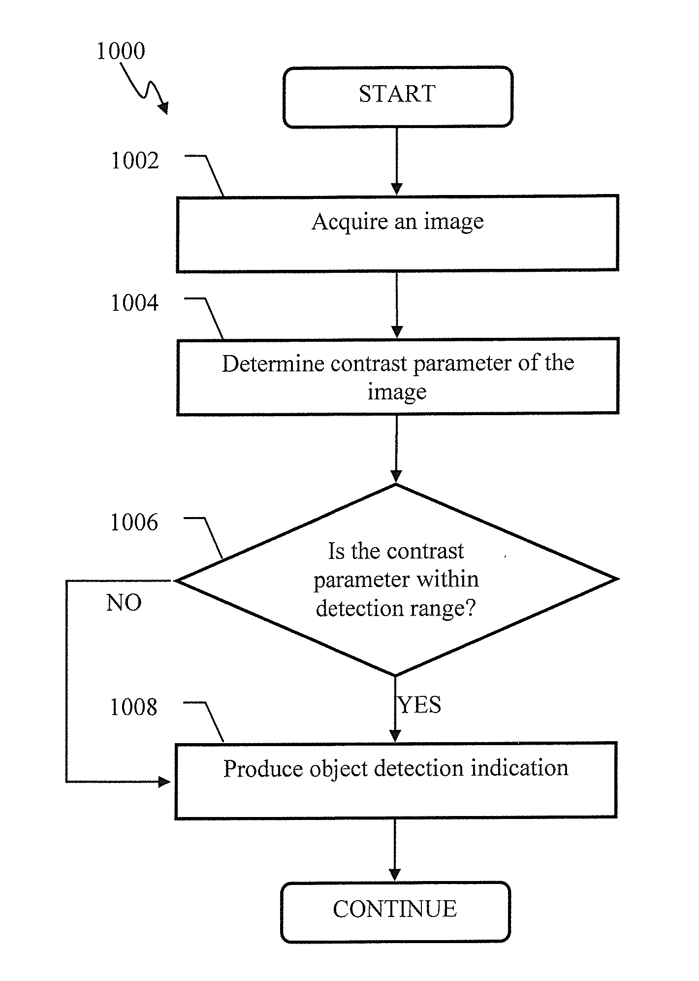
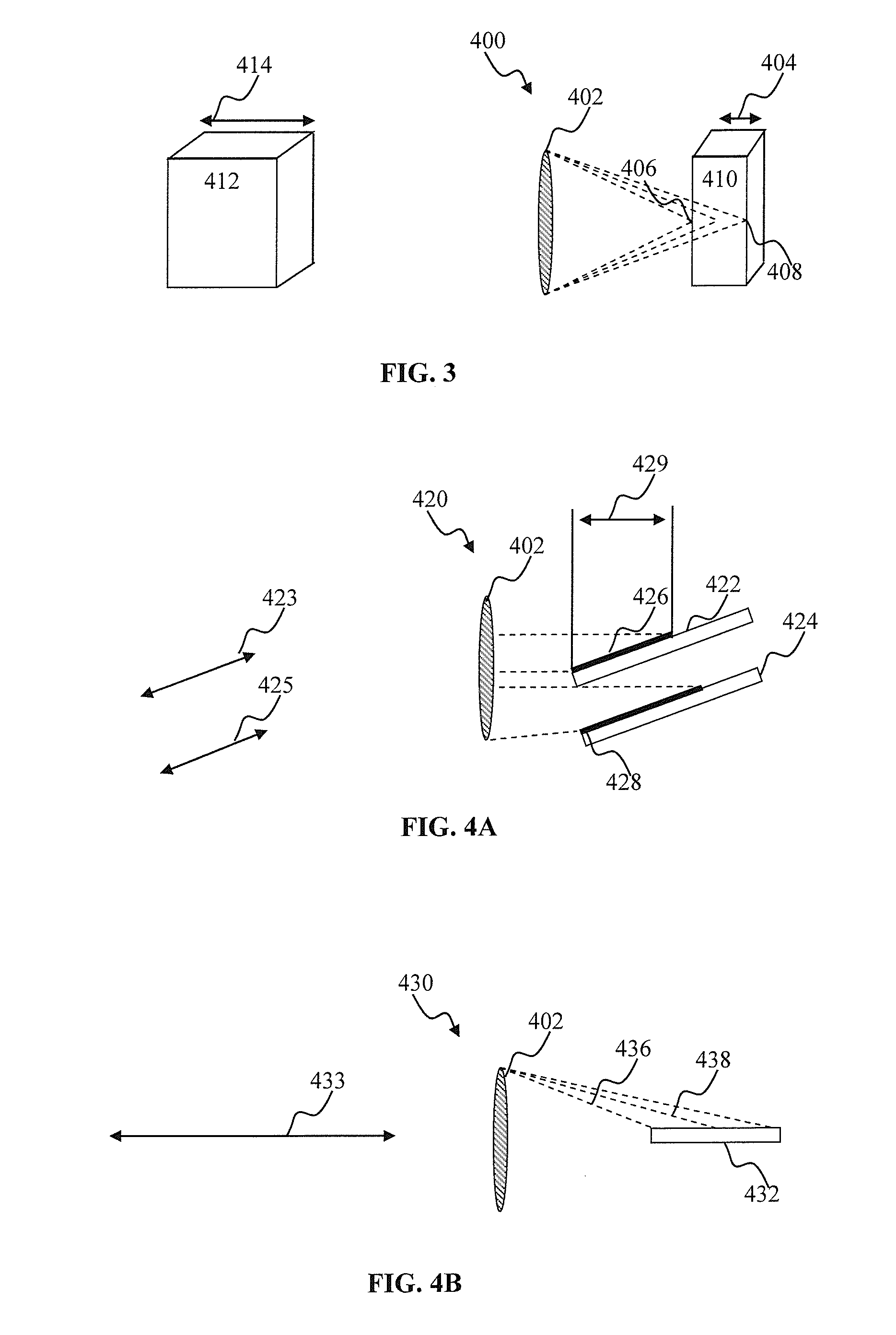
An optical object detection apparatus and associated methods. The apparatus may comprise a lens (e.g., fixed-focal length wide aperture lens) and an image sensor. The fixed focal length of the lens may correspond to a depth of field area in front of the lens. When an object enters the depth of field area (e.g., sue to a relative motion between the object and the lens) the object representation on the image sensor plane may be in-focus. Objects outside the depth of field area may be out of focus. In-focus representations of objects may be characterized by a greater contrast parameter compared to out of focus representations. One or more images provided by the detection apparatus may be analyzed in order to determine useful information (e.g., an image contrast parameter) of a given image. Based on the image contrast meeting one or more criteria, a detection indication may be produced.

Description

Copyright[0001]A portion of the disclosure of this patent document contains material that is subject to copyright protection. The copyright owner has no objection to the facsimile reproduction by anyone of the patent document or the patent disclosure, as it appears in the Patent and Trademark Office patent files or records, but otherwise reserves all copyright rights whatsoever.BACKGROUND[0002]1. Field of the Disclosure[0003]The present disclosure relates to, inter alia, computerized apparatus and methods for detecting objects or targets using processing of optical data.[0004]2. Description of Related Art[0005]Object detection may be required for target approach / obstacle avoidance by autonomous robotic devices. Small sized and / or low-cost robotic vehicles may comprise limited processing and / or energy resources (and / or weight budget) for object detection.[0006]A variety of object detection apparatus (such as IR-based, ultrasonic, and lidar) currently exist, but suffer from various di...

Claims


Application Information

Patent Timeline
Patent Type & Authority Applications(United States)
IPC IPC(8): G02B5/20G02B13/00G06V20/00H04N5/225H04N5/357H04N5/369
CPCG06K9/46G02B5/204H04N5/357G06K9/52G02B27/0075H04N5/369H04N5/2254G02B13/0015G06K9/4661G02B7/38G06V20/00G06V10/446G06V10/431H04N23/54B60W30/16B60W30/14B60W30/09G01C3/08G06V20/10G06V20/56G06V20/584H04N23/45H01L31/02162
Inventor PIEKNIEWSKI, FILIPPOLONICHKO, VADIMIZHIKEVICH, EUGENE
Owner BRAIN CORP
Learn More