
Electronic distance meter

a technology of electronic distance meter and distance meter, which is applied in the direction of distance measurement, instruments, surveying and navigation, etc., can solve the problems that the electronic distance meter may not be able to accurately calculate the round-trip time and accurately measure the distance to the target obj

Active Publication Date: 2015-12-31
KK TOPCON
View PDF3 Cites 6 Cited by
  • Summary
  • Abstract
  • Description
  • Claims
  • Application Information

AI Technical Summary

Benefits of technology

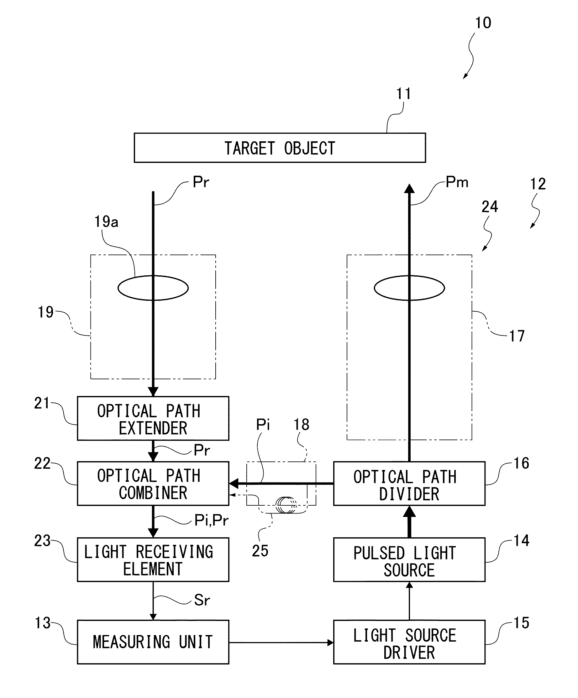
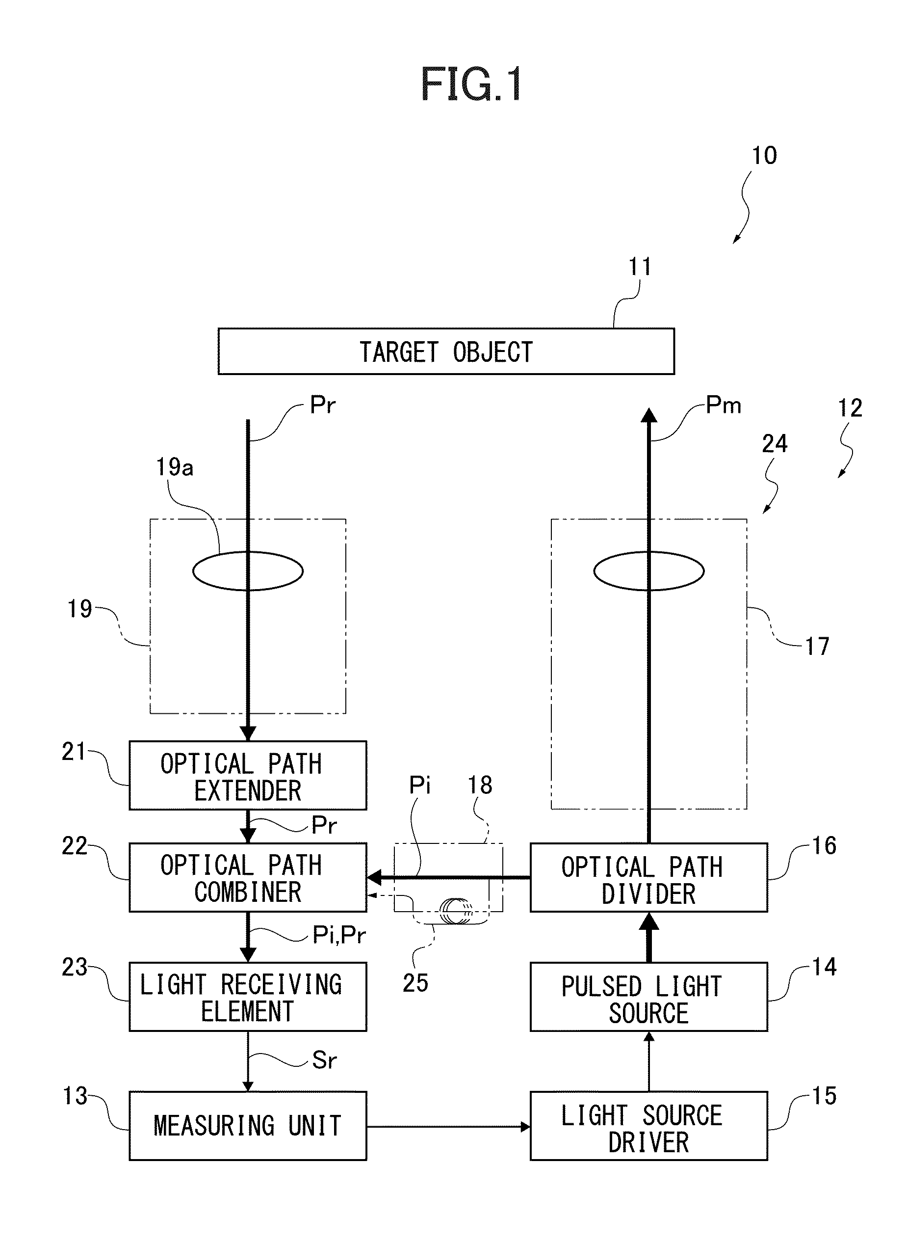
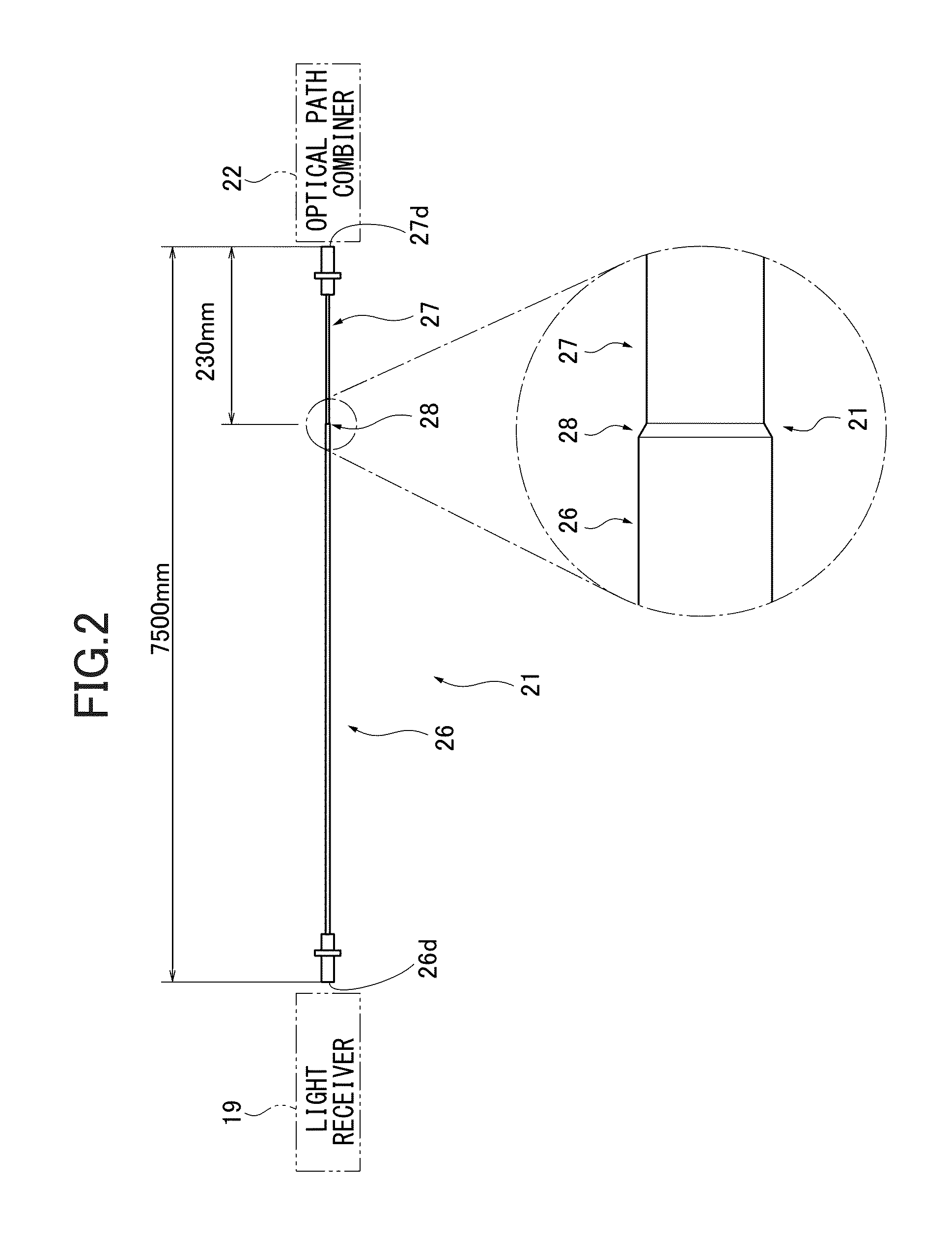
The present invention provides an electronic distance meter that can accurately measure the distance to a target object, even when the target object reflects high peak power pulsed light. The invention includes an optical unit, a measuring unit, a light receiving system, and an optical guide. The optical guide includes a multi-mode graded index fiber and a multi-mode step index fiber coupled with each other. This ensures that the light receiving element receives the reflected pulsed light without any degradation of the light receiving signal output. Therefore, the electronic distance meter can accurately calculate the round-trip time and measure the distance to the target object accurately.

Problems solved by technology

Thereby, the electronic distance meter may not be able to accurately calculate the round-trip time and accurately measure the distance to the target object.

Method used


Image

  • Electronic distance meter
  • Electronic distance meter
  • Electronic distance meter

Examples


Embodiment Construction

[0022]Hereinafter, an electronic distance meter according to one embodiment of the present invention will be described referring to the accompanying drawings.

[0023]First, one example of the structure of an electronic distance meter 10 is schematically described. As shown in FIG. 1, the electronic distance meter irradiates a target object 11 with pulsed light Pm and receives reflected pulsed light Pr diffused by the target object to obtain a round-trip time from the irradiation of the pulsed light Pm to the receipt of the reflected pulsed light Pr and measure the distance to the target object 11. The target object 11 can be various objects including furniture or interior equipment in indoor environments or structures as a building and a tunnel, trees, or landforms in outdoor environments.

[0024]The electronic distance meter 10 includes an optical unit 12 and a measuring unit 13 accommodated in a not-shown housing. The optical unit 12 is configured to emit the pulsed light Pm and recei...


PUM


Abstract

An electronic distance meter includes an optical unit which emits light to a target object and receives the light reflected by the target object with a light receiving element, a measuring unit which calculates a length of round-trip time taken for the light to make a round trip to the target object and measures a distance to the target object according to the round-trip time of the received light, a light receiving system which receives and condenses the light reflected by the target object, and an optical guide which guides the light condensed by the light receiving element to the light receiving system, including a multi-mode graded index fiber and a multi-mode step index fiber coupled with each other.

Description

CROSS-REFERENCE TO RELATED APPLICATION[0001]The present application is based on and claims priority to Japanese patent application No. 2014-131914, filed Jun. 26, 2014, the disclosure of which is hereby incorporated by reference herein in its entirety.BACKGROUND[0002]1. Technical Field[0003]The present invention relates to an electronic distance meter which irradiates a target object with light to measure a distance to a target object.[0004]2. Description of Related Art Japanese Laid-open Patent Application Publication No. 2013-11558, for example, discloses an electronic distance meter which irradiates a target object with pulsed light to measure the distance to a target object from a round-trip time taken from the light irradiation to the return of reflected pulsed light. Such an electronic distance meter irradiates a target object with pulsed light and receives reflected pulsed light diffused by the target object with a light-receiving element to obtain the round-trip time of the ...

Claims


Application Information

Patent Timeline
IPC IPC(8): G01S17/10G01S7/486
CPCG01S7/486G01S7/497G01S7/4818G01S17/10G01S17/08
Inventor NAGANO, SHIGENORITANAKA, YASUSHIYOSHINO, KENICHIRO
Owner KK TOPCON
Learn More