
Ultrasonic sensor for object and movement detection

a technology of ultrasonic sensor and object, which is applied in the direction of mechanical vibration separation, instruments, specific gravity measurement, etc., can solve the problems that conventional cmuts with vacuum backing plates cannot be used under widely varying ambient pressures, and the problem of unique challenges of flame gas metering

Inactive Publication Date: 2015-12-31
THE BOARD OF TRUSTEES OF THE LELAND STANFORD JUNIOR UNIV
View PDF11 Cites 3 Cited by
  • Summary
  • Abstract
  • Description
  • Claims
  • Application Information

AI Technical Summary

Benefits of technology

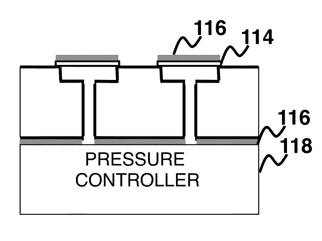
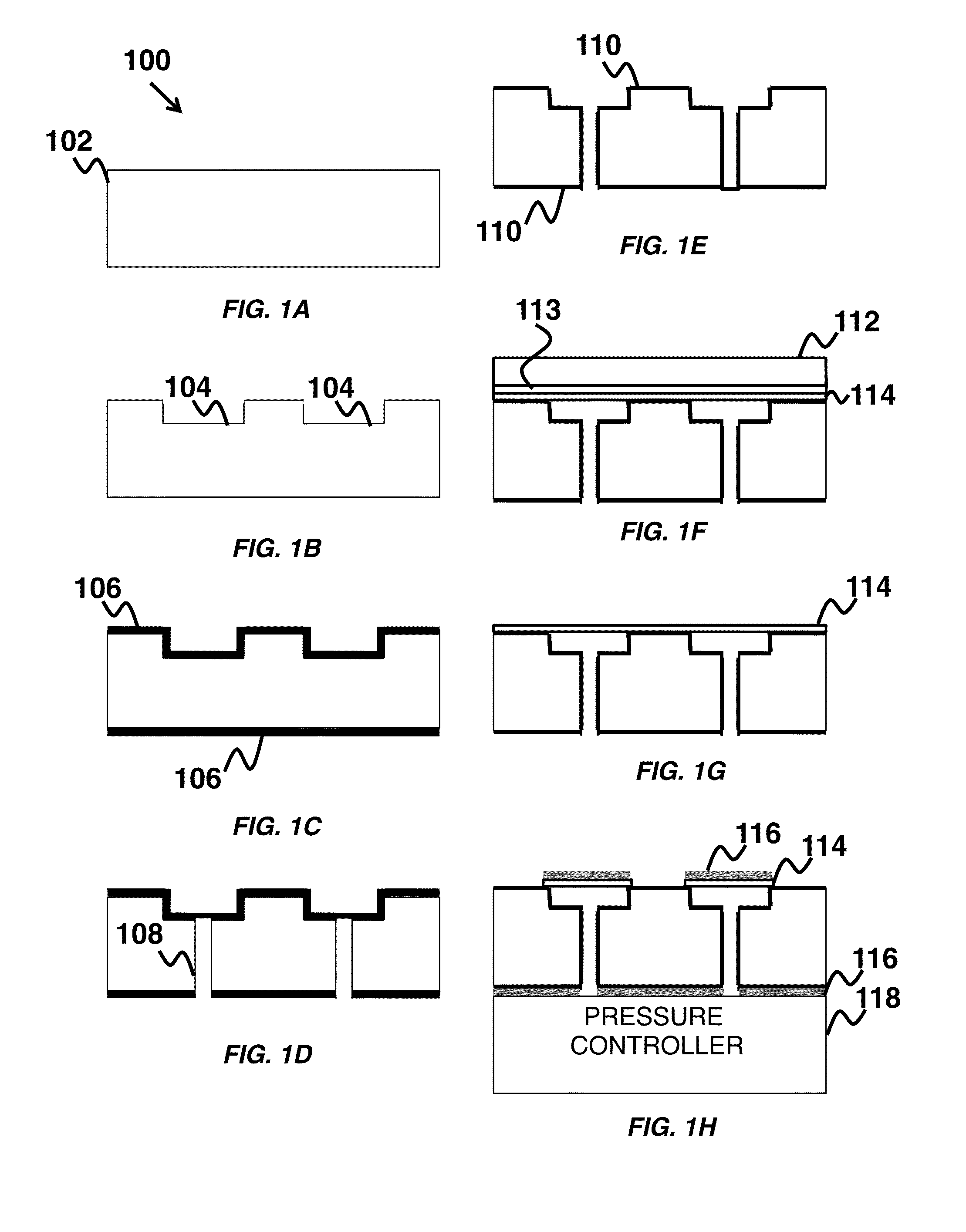
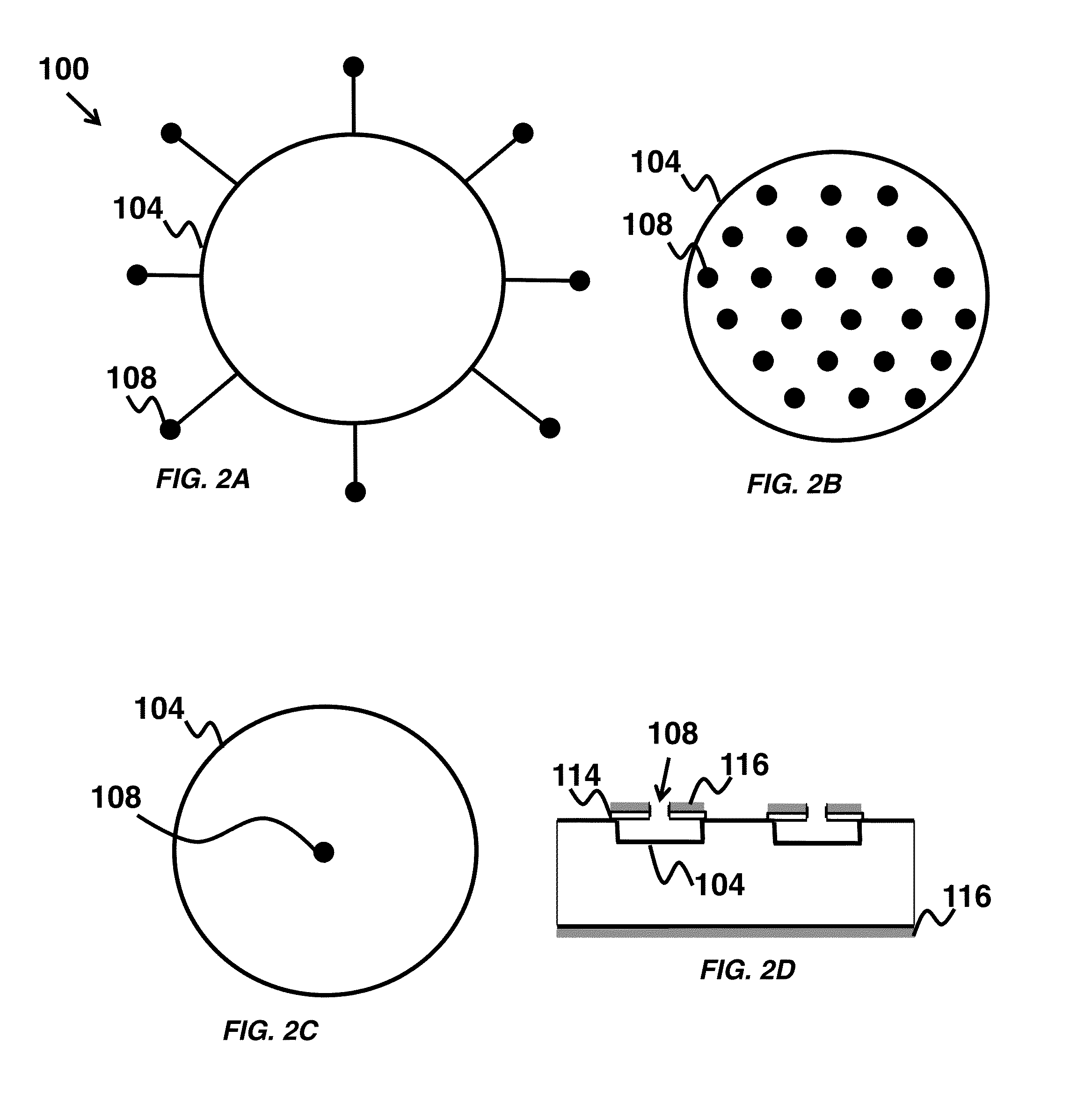
The patent describes a new type of ultrasonic transducer called a Capacitive Micromachined Ultrasonic Transducer (CMUT) that has a unique design and can operate at multiple resonance modes. The CMUT has a cavity and a plate that can vary the pressure on the plate using an active pressure controller. The pressure control can be controlled from the cavity through the bottom conductive layer or from the cavity through the CMUT plate. The CMUT can control its own signal gain and bandwidth, which can be determined by parameters like size, shape, and the location of pressure control vias. Additionally, the patent describes an array of vented CMUT elements that can transmit and receive simultaneously. Overall, the CMUT has improved performance and can be used for ultrasonic imaging and other applications.

Problems solved by technology

Flare gas metering presents unique challenges due to the large variation in the flow velocities, gas pressures and gas composition.
However conventional CMUTs with vacuum backed plates cannot be used under widely varying ambient pressures.

Method used


Image

  • Ultrasonic sensor for object and movement detection
  • Ultrasonic sensor for object and movement detection
  • Ultrasonic sensor for object and movement detection

Examples


Embodiment Construction

[0022]The current invention includes venting the cavities of CMUTs for environments with extreme pressure variations. In one embodiment, the CMUT has zero differential pressure across the plate at any ambient pressure, thus ensuring a stable operating point and preventing mechanical failure. The venting vias are etched through the substrate or throught the CMUT plate (see FIG. 2D). In one exemplary embodiment, two resonances are observed from the vented CMUTs—the mechanical resonance of the plate and an acoustic Helmholtz resonance associated with the cavity and the venting vias. Examples are provided of a variety of fabricated CMUTs having varied plate radii, thicknesses, gap heights and via arrangements to study these two resonances. In one example, a pair of CMUTs were characterized in a pitch-catch setup under varying ambient pressure. Here, the CMUTs were successfully able to transmit and receive ultrasound under an ambient pressure of up to 20 bar. As the pressure increases, t...


PUM

PropertyMeasurementUnit
pressureaaaaaaaaaa
pressureaaaaaaaaaa
distanceaaaaaaaaaa

Abstract

We provide arrays of capacitive micromachined ultrasonic transducer (CMUT) elements having large fractional bandwidth and configured such that each array element operates both to transmit and to receive. Large fractional bandwidth is provided by venting the CMUT cavity, which provides an additional source of damping for the resonant CMUT.

Description

CROSS-REFERENCE TO RELATED APPLICATIONS[0001]This application claims the benefit of U.S. provisional patent application 62 / 044,656, filed on Sep. 2, 2014, and hereby incorporated by reference in its entirety.[0002]This application is a continuation in part of U.S. Pat. No. 14 / 100,398, filed on Dec. 9, 2013, and hereby incorporated by reference in its entirety.[0003]Application Ser. No. 14 / 100,398 claims the benefit of U.S. provisional application 61 / 768,050, filed on Feb. 22, 2013, and hereby incorporated by reference in its entirety.FIELD OF THE INVENTION[0004]The present invention relates generally to Capacitive Micromachined Ultrasound Transducers (CMUTs). More particularly, the invention relates to CMUTs with pressurized cavities for operating in environments with extreme pressure variations.BACKGROUND[0005]Capacitive Micromachined Ultrasound Transducers (CMUTs) are increasingly being considered as a better alternative to traditional piezoelectric ultrasound transducers. In airb...

Claims


Application Information

Patent Timeline
Patent Type & Authority Applications(United States)
IPC IPC(8): G01N29/24
CPCG01N29/2406G01N2291/101G01N2291/044B06B1/0292
Inventor APTE, NIKHIL PRAKASHCHOE, JUNG WOOBHUYAN, ANSHUMANNIKOOZADEH, AMINKHURI-YAKUB, BUTRUS T.
Owner THE BOARD OF TRUSTEES OF THE LELAND STANFORD JUNIOR UNIV
Learn More