
Wireless power transmission to downhole well equipment

Active Publication Date: 2015-12-31
SAUDI ARABIAN OIL CO
View PDF3 Cites 46 Cited by
  • Summary
  • Abstract
  • Description
  • Claims
  • Application Information

AI Technical Summary

Benefits of technology

The present invention is a method of wireless transmitting power to downhole electrical equipment in a wellbore through well tubing. This is achieved by converting electrical power into guided wave energy at the wellhead and transferring it to the well tubing. The guided wave energy is then conducted through the walls of the well tubing to the downhole electrical equipment, where it is sensed and converted into electrical energy. This converted energy is then stored for use by the downhole electrical equipment. This technology has technical benefits in optimizing energy efficiency in wellbore operations.

Problems solved by technology

With these devices installed at depths of several thousands of feet inside a well, the use of cable was very expensive, as well as being and time-consuming to install.
The use of cable was thus undesirable.
Cable was also difficult to use in a wellbore along the tubing string whether integral to the well tubing or spaced in the annulus between well tubing and casing.
Other disadvantages of using cables included reliability issues, complicated installation, and the risk of cable breaking because of the corrosion from well fluids, as well as heavy wear due to movement of the tubing string within the wellbore.
The methods which employed a toroid for current injection in casing, tubing, or a drill string were limited in the amount of power which could be inductively coupled.
Another disadvantage of prior systems was that the wellhead necessarily had to be maintained at a very high electrical potential in order to achieve the desired current density at well bottom.
Thus, so far as is known, the prior art had limitations including high operational and design complexity, limited power transfer, low or short transmission distance and low transmission efficiency.

Method used


Image

  • Wireless power transmission to downhole well equipment
  • Wireless power transmission to downhole well equipment
  • Wireless power transmission to downhole well equipment

Examples


Embodiment Construction

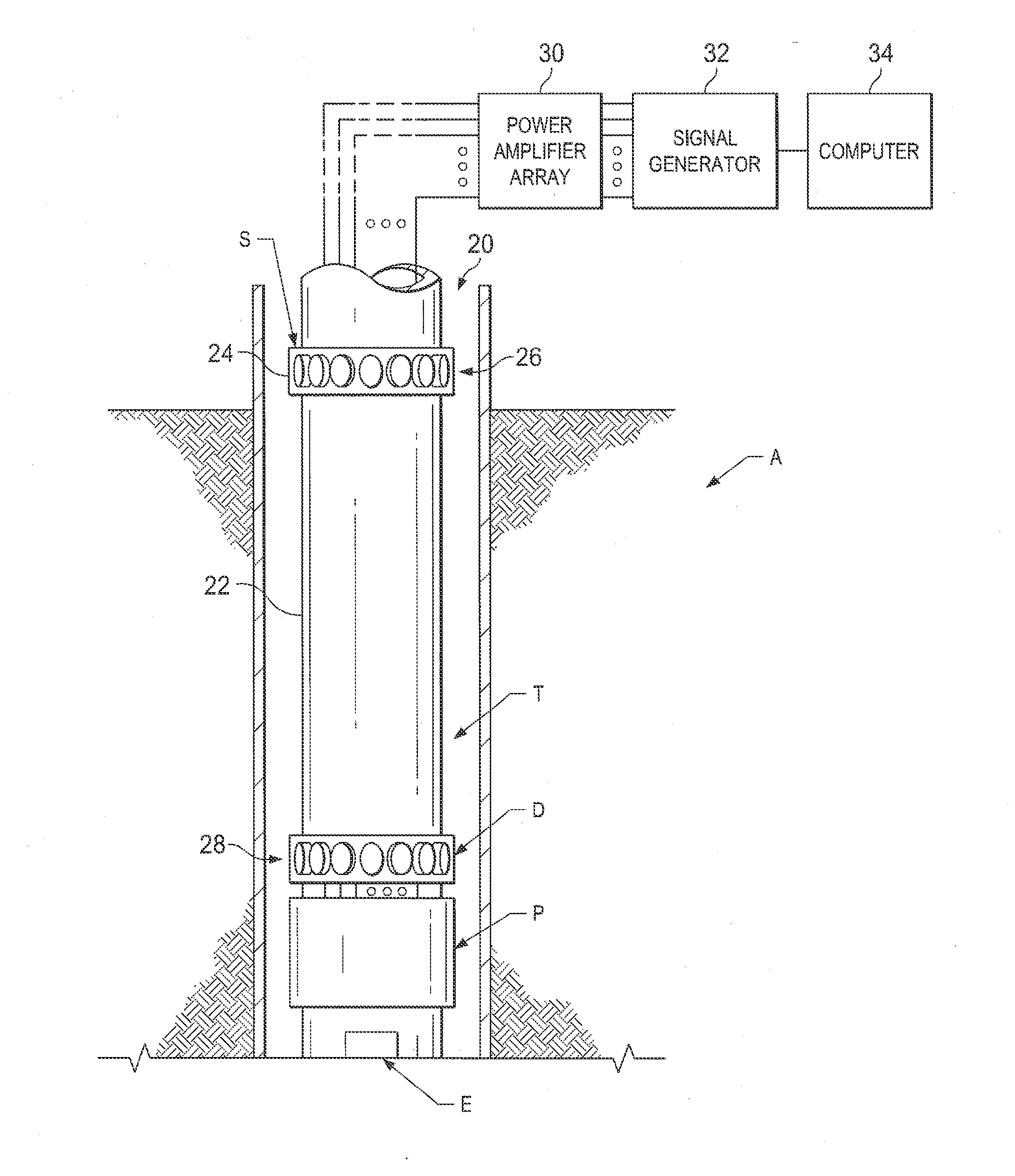
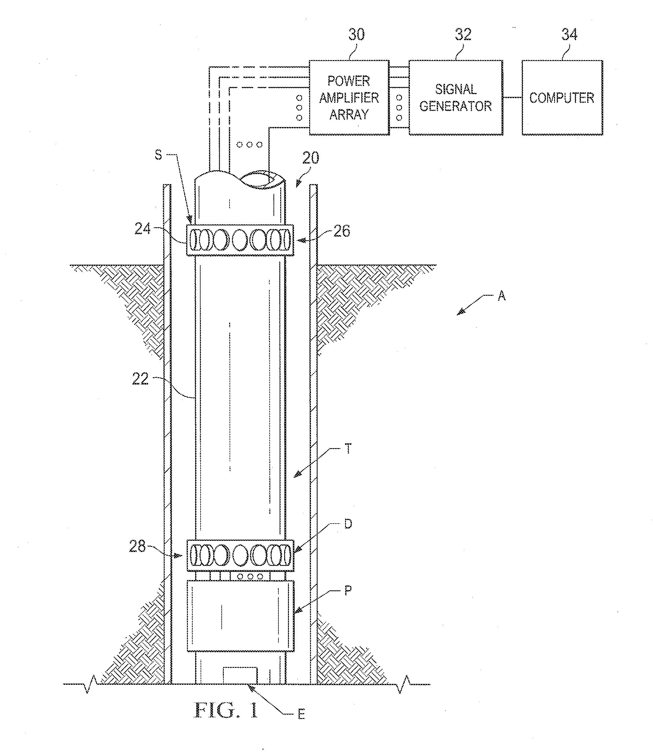
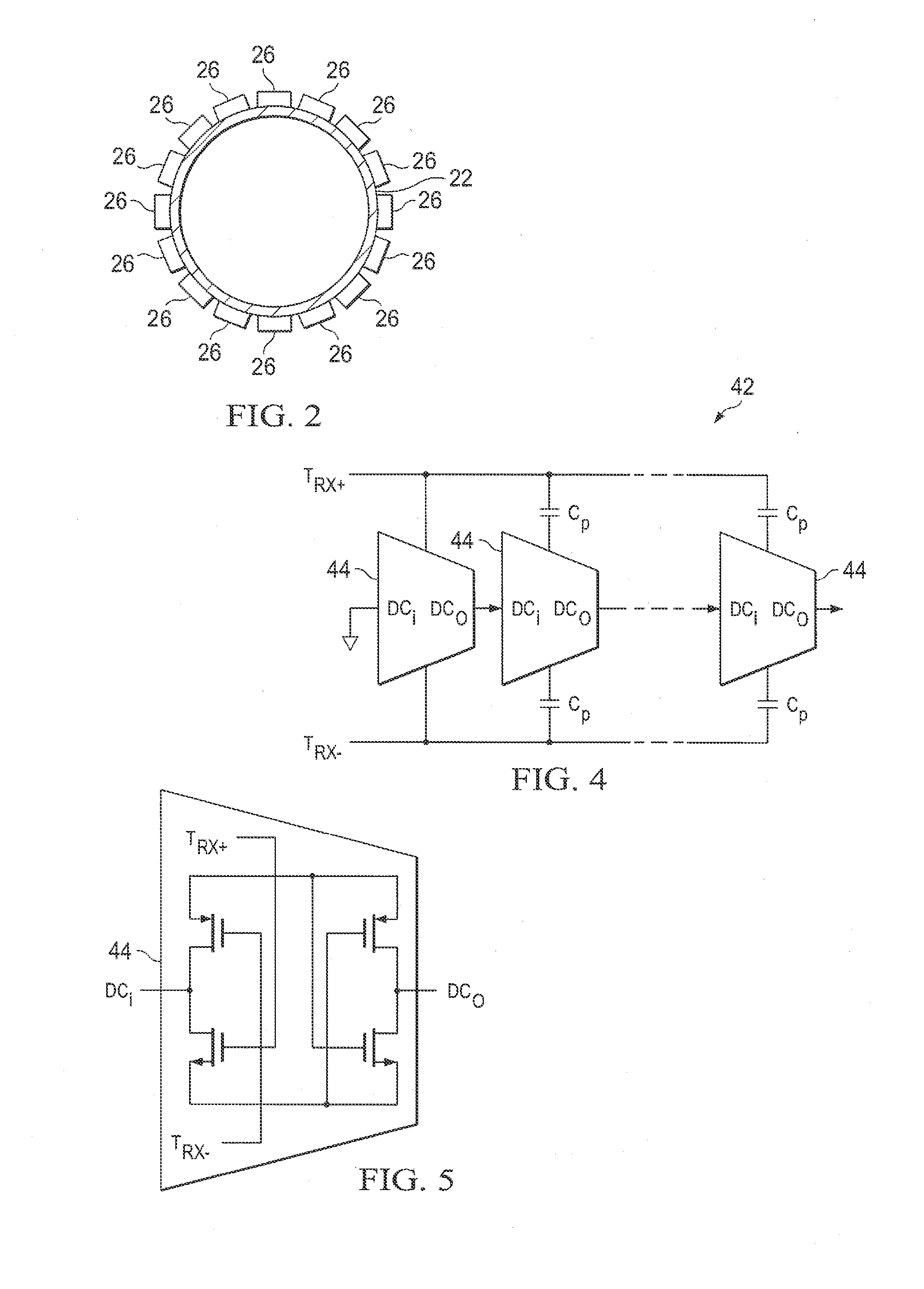
[0028]In the drawings, the letter A designates generally an apparatus according to the present invention for wireless power transmission to downhole well equipment. The apparatus A transmits acoustic guided Lamb waves are used to transfer power inside a well using production tubing or other conduit T, which may be well casing or drill string, as the transmission medium for transfer of operating power to downhole equipment E shown schematically in a wellbore 20. The downhole well equipment E may take the form of sensors located in the wellbore 20 or mounted on the tubing T. The sensors acquire real-time data from reservoir formations of interest adjacent the wellbore 20 for continuous or automated reservoir management. The downhole well equipment E may also take the form of electromechanical flow control mechanisms such as valves to adjust fluid flow in wellbore 20.

[0029]The apparatus A includes a surface transducer module S which has a mounting frame or collar 24 containing an array...


PUM


Abstract

Wireless power transmission to downhole well installations is provided using acoustic guided Lamb waves and a tubular conduit (production tubing, casing) as the power transmission medium. A phased array of acoustic transmitters is present at the transmitting end (surface) and an array of acoustic receivers at the receiving end (downhole). Both transmitter and receiver arrays are coupled to the tubular conduit. Beamforming techniques are used along with power amplifiers to generate directional, high power and low frequency acoustic guided Lamb waves along the wellbore to transmit power over long distances. A downhole multi-channel acoustic energy collecting system receives the transmitted acoustic signal, and generates electrical power and stores the power in downhole electrical power storage. This power is used to operate downhole well equipment including sensing, control and telemetry devices.

Description

[0001]This application claims priority from U.S. Provisional Application No. 62 / 018,749, filed Jun. 30, 2014. For purposes of United States patent practice, this application incorporates the contents of the Provisional Application by reference in entirety.BACKGROUND OF THE INVENTION[0002]1. Field of the Invention[0003]The present invention relates to wireless power transmission in oil wells to downhole well equipment, using guided acoustic Lamb waves and with tubular conduits in the well serving as a power transmission medium.[0004]2. Description of the Related Art[0005]Reservoir management has been based on acquiring reservoir data captured by permanently installed sensors inside a well. These sensors were directly in contact with the reservoir to be monitored and provided real-time data concerning reservoir conditions for long-term and continuous reservoir management. One such reservoir management system is a permanent downhole monitoring system, or PDHMS, utilized by the assignee...

Claims


Application Information

Patent Timeline
IPC IPC(8): E21B47/12
CPCE21B47/16E21B41/0085
Inventor AHMAD, TALHA JAMAL
Owner SAUDI ARABIAN OIL CO
Learn More