
Knuckle bracket and pair of knuckle brackets

a technology of knuckle brackets and knuckle brackets, which is applied in the direction of shock absorbers, machine supports, transportation and packaging, etc., can solve the problems of increased labor requirements, and achieve the effect of preventing assembly mistakes, increasing labor requirements, and improving identification accuracy

Active Publication Date: 2015-12-31
KYB CORP
View PDF15 Cites 0 Cited by
  • Summary
  • Abstract
  • Description
  • Claims
  • Application Information

AI Technical Summary

Benefits of technology

The patent text describes a method to prevent assembly mistakes when attaching knuckle brackets to a shock absorber. This is done by adding marks on the knuckle brackets for easy visual identification and using a device that mechanically identifies the type of knuckle bracket. This ensures that the knuckle brackets are assembled correctly. The method also involves welding the knuckle brackets to the outer tube of the shock absorber and correcting the width dimension between the gripping pieces using a jig. The technical effects of this method include improved assembly accuracy and efficiency.

Problems solved by technology

However, differences may occur in how the gripping pieces warp depending on the presence or absence of the cut-away part C. Therefore, it is necessary to prepare different jigs for the right-side knuckle bracket and the left-side knuckle bracket, and the required labor increases because the jigs must be exchanged.

Method used


Image

  • Knuckle bracket and pair of knuckle brackets
  • Knuckle bracket and pair of knuckle brackets
  • Knuckle bracket and pair of knuckle brackets

Examples


Embodiment Construction

[0017]A knuckle bracket according to an embodiment of the present invention will now be explained below referring to the drawings.

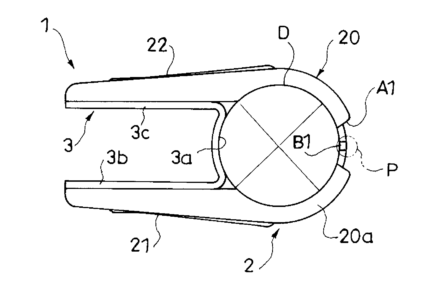
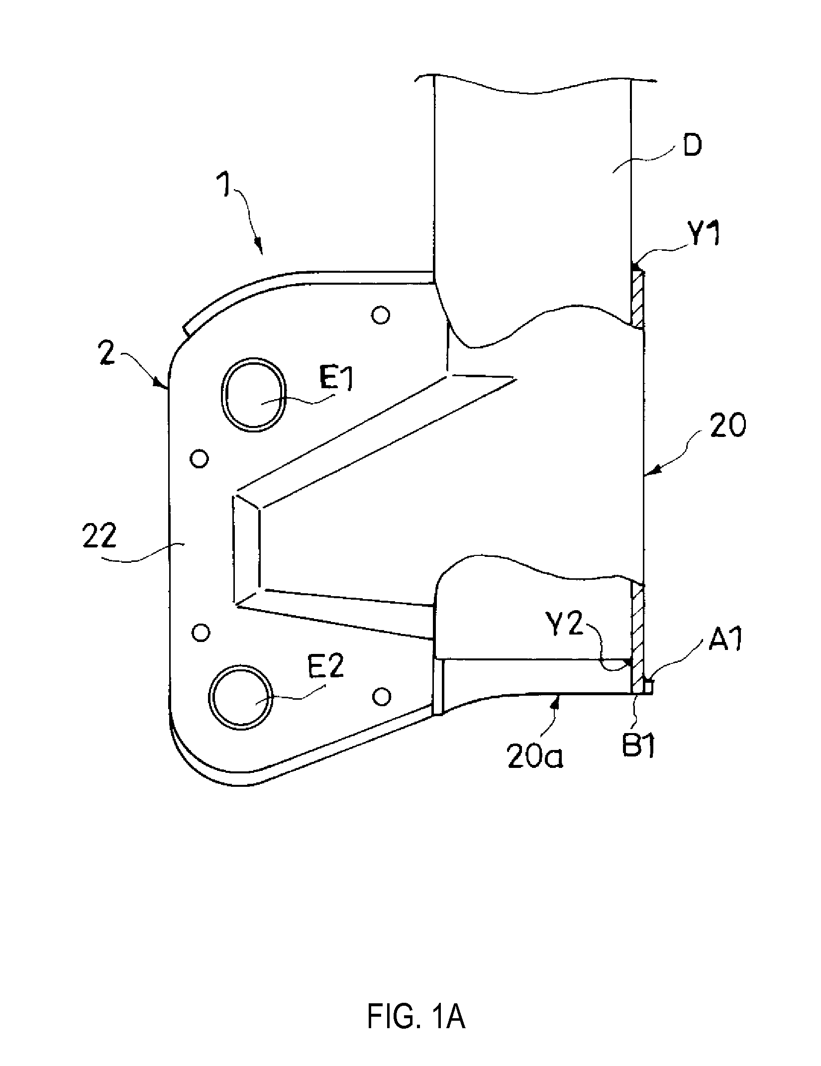
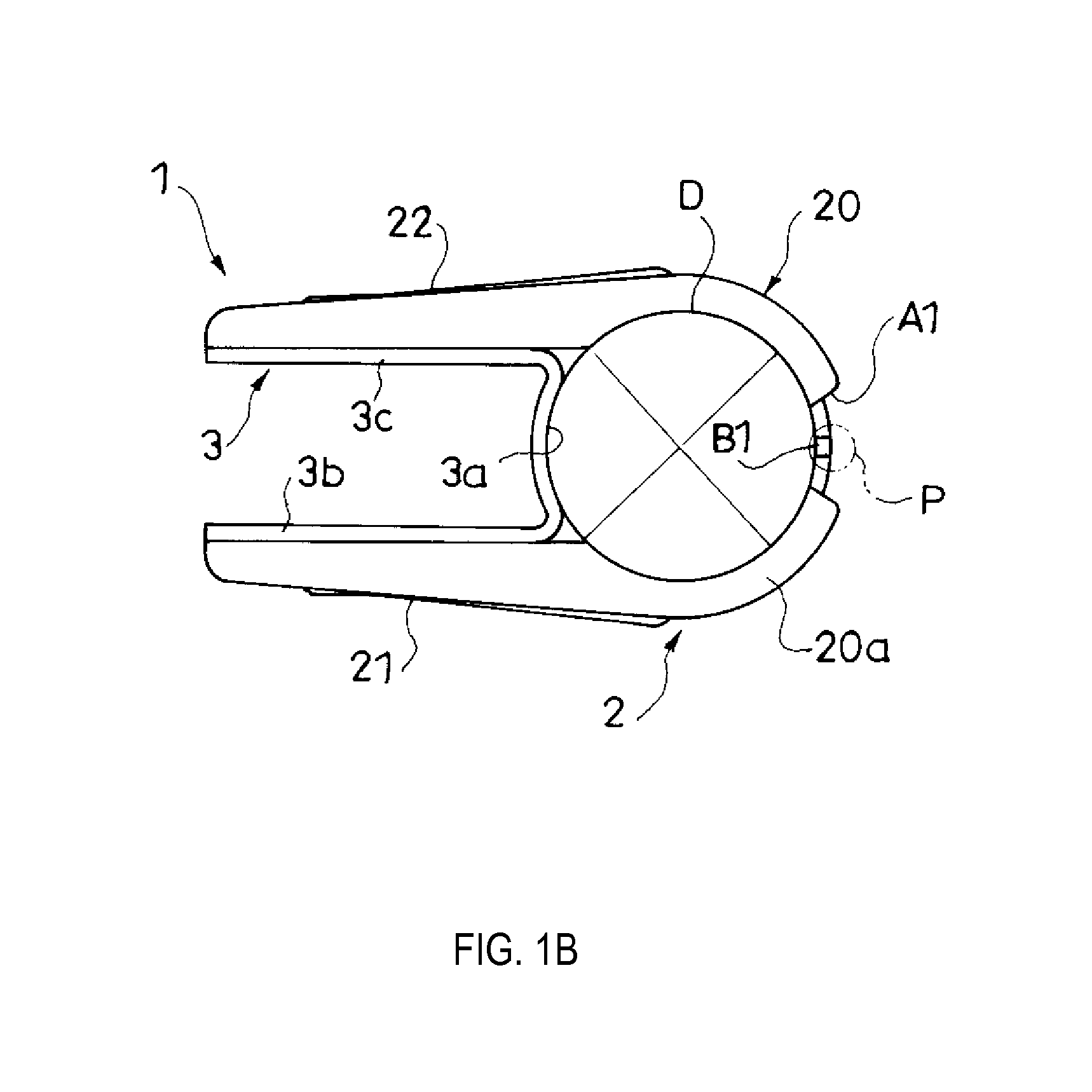
[0018]As shown in FIGS. 1A and 1B, a knuckle bracket 1 includes a cylindrical bracket main body 20 that is fixed by welding to an outer periphery of an outer tube D of a shock absorber, a pair of gripping pieces 21 and 22 that extend along an axial direction of the bracket main body 20 and stand up toward the outside from the bracket main body 20 opposing each other. Further, the bracket main body 20 has a cut-away part A1 formed on a lower end (one side end) 20a, and a compression part B1 that is abutted by a misassembly detection pin P of a misassembly prevention device that identifies the type of the knuckle bracket 1.

[0019]The knuckle bracket 1 is used in a strut-type suspension that utilizes a shock absorber as a support column for positioning the wheel of an automobile, and is attached to the outer periphery of the outer tube D of the shock absorber...


PUM


Abstract

A knuckle bracket includes a cylindrical bracket main body that is fixed by welding to an outer periphery of an outer tube of a shock absorber and a pair of gripping pieces that extend along an axial direction of the bracket main body and stand up toward the outside from the bracket main body opposing each other. The bracket main body has a cut-away part formed on one side end and a compression part, the compression part being configured to abut a misassembly detection pin of a misassembly prevention device, the misassembly prevention device being configured to identify a type of the knuckle bracket.

Description

TECHNICAL FIELD[0001]The present invention relates to a knuckle bracket and a pair of knuckle brackets.BACKGROUND ART[0002]JP2007-45282A and JP2007-320332A disclose a knuckle bracket including a cylindrical bracket main body that is fixed by welding to an outer periphery of an outer tube of a shock absorber, and a pair of gripping pieces that extend along an axial direction of the bracket main body and stand up toward the outside from the bracket main body opposing each other. The knuckle bracket is used in a strut-type suspension. The strut-type suspension is connected to a knuckle that retains a vehicle wheel so that it can rotate via the gripping pieces of the knuckle bracket.SUMMARY OF INVENTION[0003]Normally, a shock absorber of a strut-type suspension is differentiated into a right-side shock absorber disposed on the right side of the vehicle and a left-side shock absorber disposed on the left side of the vehicle, and the right-side shock absorber and the left-side shock absor...

Claims


Application Information

Patent Timeline
Patent Type & Authority Applications(United States)
IPC IPC(8): B60G3/06
CPCF16F9/3242F16F9/54B60G3/06B60G13/008B60G2204/4304B60G2204/43B60G13/005B60G2200/142
Inventor ASAOKA, SHOTAROSETOGUCHI, KAZUHIROHOSHINO, YUTA
Owner KYB CORP
Learn More