Plasma processing apparatus and plasma processing method

Active Publication Date: 2015-12-24
HITACHI HIGH-TECH CORP
View PDF11 Cites 9 Cited by
  • Summary
  • Abstract
  • Description
  • Claims
  • Application Information

AI Technical Summary

Benefits of technology

The patent is about a plasma processing apparatus that uses RF power to create a bias in a sample on a stage. The problem to be solved is how to efficiently match the impedance of the RF power supply and the plasma to remove or reduce reflection of the RF power. The solution leads to improved reproducibility, reduced power loss and damage, and an improvement in etching processing reproducibility.

Problems solved by technology

In the above-described related art, problems are caused because consideration concerning aspects described below is insufficient.
Even if it is attempted to change impedance by mechanical control in a circuit implementing matching, it becomes actually difficult to implement matched impedance in correspondence to each of varying output values following the period of variation.
This results in a problem that the RF power supply or elements in a circuit for matching generate heat or are eventually damaged due to power of the reflected wave.

Method used


Image

  • Plasma processing apparatus and plasma processing method
  • Plasma processing apparatus and plasma processing method
  • Plasma processing apparatus and plasma processing method

Examples


embodiment

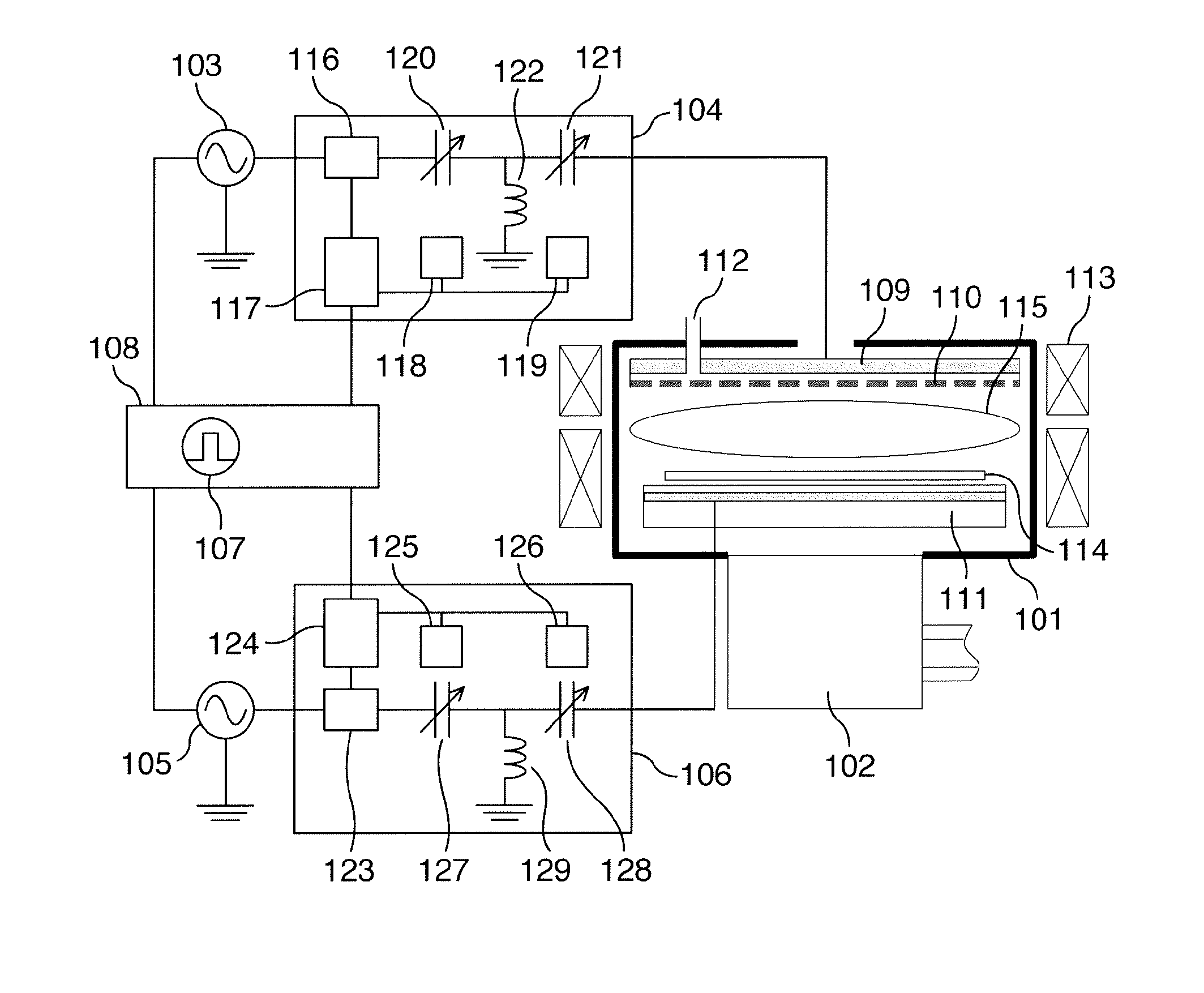
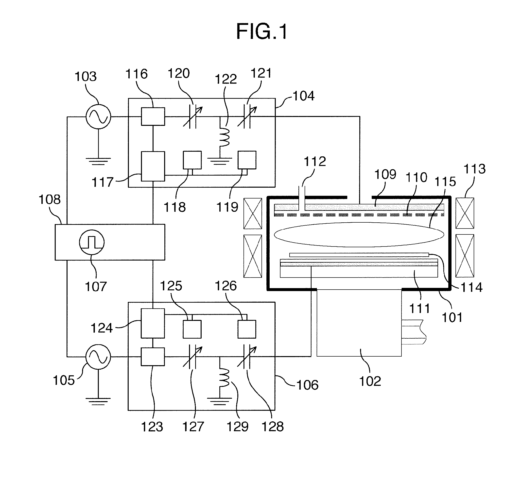
[0022]An embodiment of the present invention will now be described with reference to FIGS. 1 to 6FIG. 1 is a longitudinal sectional view schematically showing an outline of a configuration of a plasma processing apparatus according to the embodiment of the present invention.

[0023]The plasma processing apparatus shown in FIG. 1 is broadly divided into a vacuum vessel having an internal space depressurized to a predetermined degree of vacuum, an electromagnetic field supply unit disposed over the vacuum vessel to supply an electric field or a magnetic field and thereby form plasma within the vacuum vessel, and an exhaust unit including a vacuum pump such as a turbomolecular pump 102 or a roughing vacuum pump disposed under the vacuum vessel to evacuate the inside of the vacuum vessel. The vacuum vessel is a vessel made of metal having a processing chamber 101 which is cylindrically shaped to provide a space in which a substrate-shaped sample such as a semiconductor wafer of a processi...


PUM

PropertyMeasurementUnit
Ratioaaaaaaaaaa
Electric fieldaaaaaaaaaa
Electric impedanceaaaaaaaaaa

Abstract

A plasma processing apparatus is provided including a processing chamber disposed within a vacuum vessel to form plasma therein, a processing stage disposed in the processing chamber to mount a wafer thereon, a first power supply for outputting an electric field supplied to form the plasma and forming an electric field of a first frequency supplied with repetition of a high output and a low output during processing of the wafer, a second power supply for supplying power of a second frequency to an electrode disposed within the processing stage, and a control device for causing a first value between load impedance at time of the high output of the electric field and load impedance at time of the low output of the electric field to match with impedance of the first power supply.

Description

BACKGROUND OF THE INVENTION[0001]The present invention relates to a plasma processing apparatus and a plasma processing method, and in particular to a plasma processing method of conducting a matching operation with respect to a radio frequency (RF) power supply having periodical repetition of a high output period and a low output period.[0002]In recent years, further high precision of working has been demanded in etching processing using plasma with the progress of miniaturization and integration of semiconductor devices. As a solution for such a problem, it has been known from the past that selectivity of a film of a processing target formed in advance on a top surface of a sample can be improved by changing with lapse of time (temporally), the magnitude or frequency of RF power applied to a sample or electrodes within a sample stage which holds the sample, in order to form bias potential over the sample, or changing power which forms an electric field supplied to form plasma, i.e...

Claims


Application Information

Patent Timeline
IPC IPC(8): H01L21/67H01L21/3213H01L21/311H01J37/32H01L21/3065
CPCH01L21/67069H01J37/32183H01J37/32532H01J2237/334H01L21/31116H01L21/31138H01L21/32136H01L21/3065H01J37/32082H01J37/32174H01J37/3299
Inventor TERAUCHI, HIROMITSUIIDA, TSUTOMUYAMAMOTO, KOICHI
Owner HITACHI HIGH-TECH CORP
Why Eureka
Try Eureka