
High rotational momentum disperser and use

a disperser and high rotational momentum technology, applied in the direction of lighting and heating equipment, separation processes, furnaces, etc., can solve the problems of time-consuming and costly cleaning and maintenance of the system and/or plant, plant or system shut down, and scale buildup, so as to prolong the penetration of droplets and reduce the consumption of absorbent materials.

Active Publication Date: 2015-12-24
GENERAL ELECTRIC TECH GMBH
View PDF1 Cites 7 Cited by
  • Summary
  • Abstract
  • Description
  • Claims
  • Application Information

AI Technical Summary

Benefits of technology

The patent is about a system for removing gas pollutants from hot flue gas. It includes a large spray dryer absorption vessel with a high rotational momentum disperser. The disperser helps to break down the flue gas into small droplets, which can then be absorbed by a reagent slurry in the absorption vessel. The system is designed to have a high efficiency in removing pollutants, while reducing the amount of absorbent material needed. This results in a more cost-effective and efficient process for gas purification.

Problems solved by technology

Delivery of a reagent slurry or solution to an atomizer system such as one or more of those described above, in combination with a dilution liquid, typically results in scale buildup.
Scale buildup causes plant or system shut downs for necessary cleaning and / or maintenance.
Plant or system shut downs, as well as the related cleaning and maintenance of the system and / or plant, is time consuming and costly.
Further, in the case of larger capacity SDA vessels of approximately 12 to approximately 22 meters or larger in diameter, which are desirable to reduce capital expenditures and reduce equipment footprint requirements, scale buildup is even a greater issue.
Current dispersers do not allow slurry droplets to penetrate the flue gas sufficiently under higher volume flue gas stream flow as characteristic through the larger capacity SDA vessels.
Droplet spray cloud suppression in turn causes poor contact between the reagent slurry and flue gas, resulting in low SOx removal efficiency.
Attempts to address low SOx removal efficiency by using an increased number of dispersers within the larger capacity SDA vessels of approximately 12 to approximately 22 meters or larger in diameter, results in additional problems.
Such additional problems include intense droplet impactions on vessel walls and significant scale buildup thereon with associated high reagent consumption and cost.

Method used


Image

  • High rotational momentum disperser and use
  • High rotational momentum disperser and use
  • High rotational momentum disperser and use

Examples


Embodiment Construction

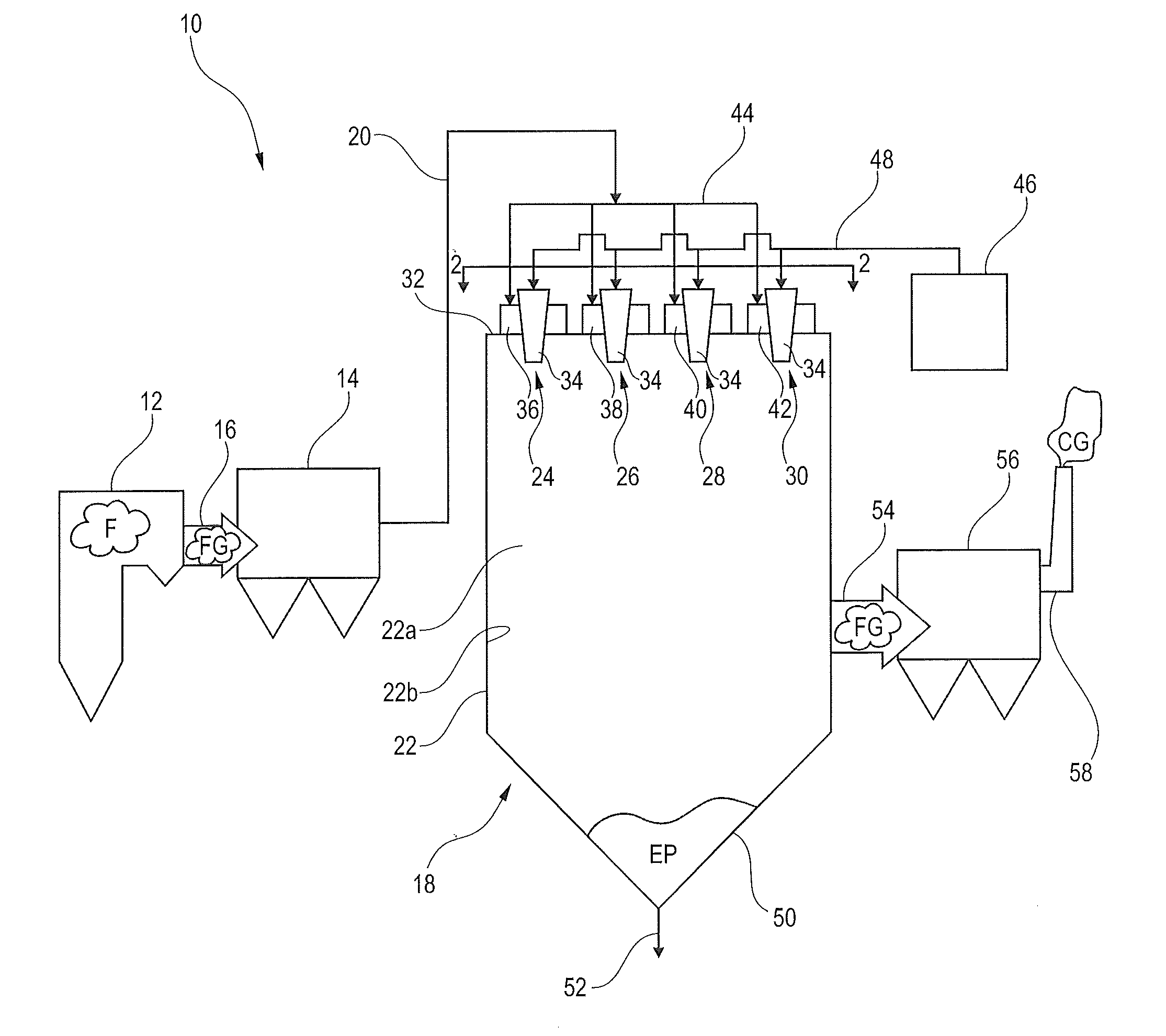
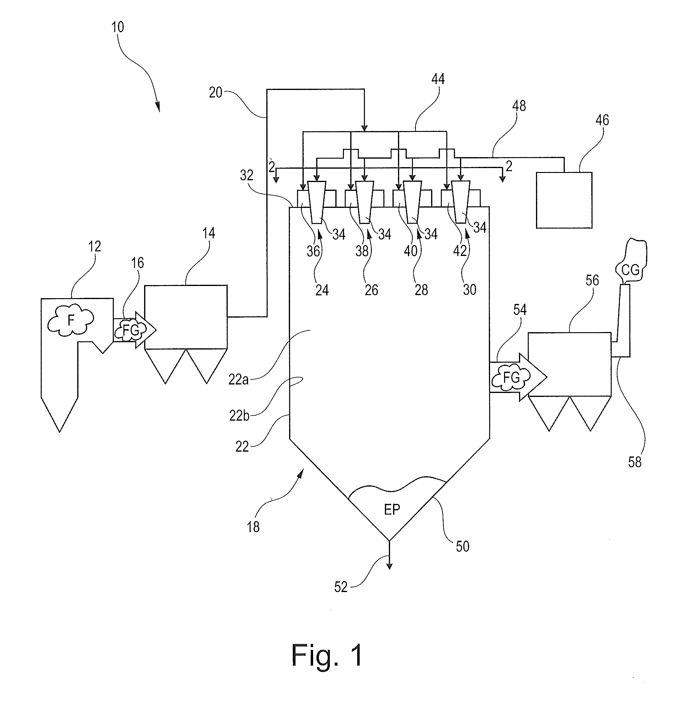
[0029]FIG. 1 is a schematic side view illustrating a power plant 10. The power plant 10 comprises a boiler 12 in which a fuel F, such as coal or oil, is combusted. The combustion of the fuel generates a hot process gas in the form of a flue gas FG. Sulphur species contained in the coal or oil produce upon combustion sulphur dioxide, which forms part of the flue gas FG. The flue gas FG flows from the boiler 12 to a fluidly connected electrostatic precipitator 14 via a duct 16. The electrostatic precipitator 14, an example of which is described in U.S. Pat. No. 4,502,872, the teachings of which incorporated herein by reference, serves to remove dust particles from the flue gas FG.

[0030]Flue gas FG, from which most of the dust particles have been removed, then flows to a fluidly connected spray dryer absorber (SDA) system 18 via a fluidly connected duct 20. The SDA system 18 comprises a relatively larger capacity SDA vessel 22 of approximately 12 to approximately 22 meters or larger in...


PUM

PropertyMeasurementUnit
Fractionaaaaaaaaaa
Angleaaaaaaaaaa
Angleaaaaaaaaaa

Abstract

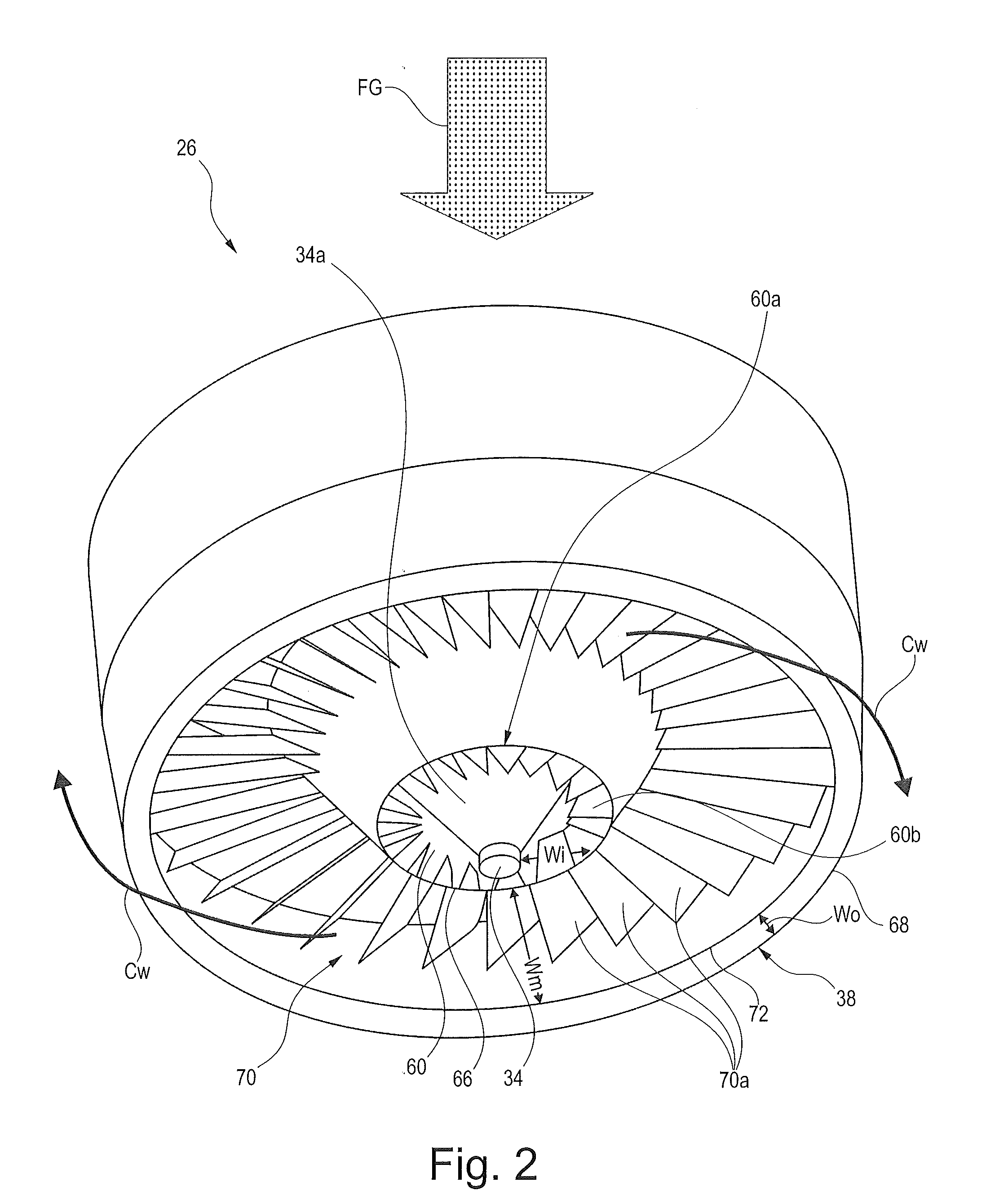
A spray dryer disperser 24, 26, 28, 30 is described for use in a spray dryer absorption (SDA) system 18 for flue gas FG impurity reduction. As such, the spray dryer disperser 24, 26, 28, 30 disperses absorbent liquid or reagent slurry droplets into contact with a hot flue gas FG stream containing gaseous impurities to produce a flue gas FG stream of reduced impurity content and dry powder end products EP. The spray dryer disperser 24, 26, 28, 30 is useful in larger capacity SDA vessels 22 of approximately 12 to 22 meters in diameter or larger, to avoid disperser 24, 26, 28, 30 shroud 34a scale deposits, to avoid reagent slurry spray cloud suppression, to avoid vessel 22 wall 22b scale deposits and to achieve increased droplet rotational momentum for increased droplet flue gas FG penetration for efficient impurity reduction.

Description

FIELD OF THE DISCLOSURE[0001]The present disclosure relates to a spray dryer disperser for use in a spray dryer absorption (SDA) system for contacting a hot flue gas stream containing gaseous impurities with an absorbent material to produce a flue gas stream of reduced impurity content and dry powder products. More specifically, the present disclosure relates to a relatively high rotational momentum disperser for use in a relatively larger capacity SDA vessel of approximately 12 to approximately 22 meters or larger in diameter, that avoids disperser shroud deposits, avoids spray cloud suppression, avoids vessel wall deposits and achieves extended droplet penetration for required impurity removal efficiency with reduced absorbent material consumption.BACKGROUND OF THE DISCLOSURE[0002]Combustion of fuel, particularly carbonaceous materials such as fossil fuels and waste, results in hot flue gas streams that contain impurities, such as mercury (Hg), sulfur oxides (SOx), nitrogen oxides...

Claims


Application Information

Patent Timeline
IPC IPC(8): B01D53/79B01D53/18
CPCB01D53/185B01D53/79B01D53/504B01D53/505B05B7/10B05B15/55F26B3/12
Inventor RAFIDI, NABIL ELIAS
Owner GENERAL ELECTRIC TECH GMBH
Learn More