
Double-action pusher centrifuge and pusher base device

a pusher and centrifuge technology, applied in centrifuges, turbine/propulsion air intakes, air transportation, etc., can solve problems such as negative effects on the quality of the produced solid cake, and achieve the effect of reducing wear

Active Publication Date: 2015-12-24
FERRUM PROCESS SYST AG
View PDF1 Cites 3 Cited by
  • Summary
  • Abstract
  • Description
  • Claims
  • Application Information

AI Technical Summary

Benefits of technology

The invention improves a double-action pusher centrifuge by reducing the sudden acceleration of the mixture being dehumidified. It achieves this by creating an inflow gap between the inflow edge of the inflow disk and the pusher base plate, allowing the mixture to flow more smoothly and gently. Additionally, a distribution ring can be added to evenly distribute the mixture in the peripheral direction. To minimize wear, wear rings can also be provided at the outer ring region.

Problems solved by technology

In particular with sensitive substances, this can inter alia result in grain fracture, that is that, for example solid grains which are distributed in a suspension supplied to the centrifuge, burst into smaller pieces in an uncontrolled manner on the abrupt acceleration process, which can have negative effects on the quality of the produced solid cake if, for example, the particle size of the grains in the end product plays a role.

Method used


Image

  • Double-action pusher centrifuge and pusher base device
  • Double-action pusher centrifuge and pusher base device
  • Double-action pusher centrifuge and pusher base device

Examples


first embodiment

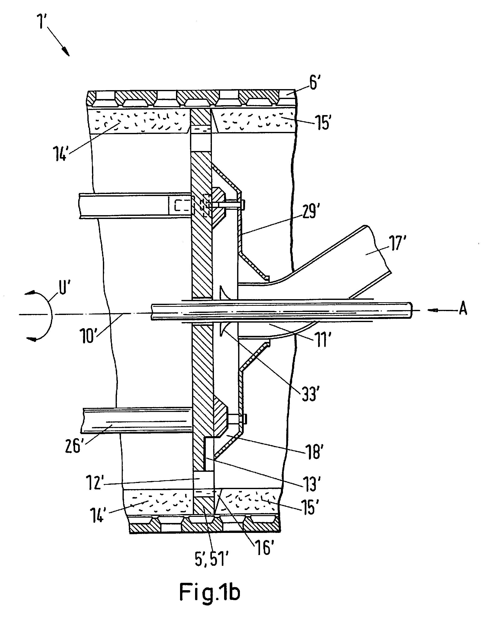
[0048]FIG. 2 shows in section in a highly schematic representation, major components of a double-action pusher centrifuge in accordance with the invention by way of example. In this respect, the double-action pusher centrifuge of the present invention can be considered as a further development of the known double-action pusher centrifuge in accordance with FIG. 1a-FIG. 1d at least for special embodiments, with the major difference being able to be seen in the inflow gap which is not interrupted in the peripheral direction and which is lacking in the known double-action pusher centrifuges.

[0049]The double-action pusher centrifuge in accordance with the invention of FIG. 2, which is designated by the reference numeral 1 in total, serves for the separation of a mixture 17 into a solid cake 14, 15 and into a liquid 39.

[0050]The double-action pusher centrifuge 1 comprises in a manner known per se a screen drum 6 which is rotatable about an axis of rotation 10 and in which a pusher base d...

second embodiment

[0052]FIG. 3 shows a double-action pusher centrifuge 1 in accordance with the invention in which in contrast to the example of FIG. 2 the inflow groove 531 is missing and instead the inflow gap 53 is formed as a spacing gap 532 between the inflow edge 291 and the pusher base plate 52, with the remaining components of the double-action pusher centrifuge 1 of FIG. 3 otherwise in principle being configured analog to the corresponding components of the double-action pusher centrifuge 1 in accordance with FIG. 2.

third embodiment

[0053]FIG. 4 shows a third embodiment having a distribution ring 502 and a preacceleration device 501. The preacceleration device 501 in this respect serves for the further improvement of the preacceleration of the mixture 17 in the inlet region 500 of the pusher base device 5. The vanes of the preacceleration device 501 can in this respect, for example, be formed spirally outside the feed unit 11. In addition, a distribution ring 502 is provided between the preacceleration device 501 and the screen drum 6 at a somewhat larger diameter in the inflow region 500. The distribution ring 502 in this respect allows an even more uniform distribution of the mixture over the pusher base plate 52. It is self-explanatory in this respect that in very specific embodiments, only the distribution ring 502 or only the preacceleration device 501 can also be present and both the distribution ring 502 and the preacceleration device 501 can e.g. also advantageously be used in an embodiment in accordanc...


PUM

PropertyMeasurementUnit
displacementaaaaaaaaaa
heightaaaaaaaaaa
frictionaaaaaaaaaa

Abstract

A double-action pusher centrifuge separates a mixture into solid cake and liquid. The pusher centrifuge includes a screen drum rotatable about an axis and in which a pusher base device is arranged to be movable along the axis of rotation. The solid cake is displaced by an outer ring region of the pusher base device. A plurality of axial passage openings are disposed in the outer ring region and connect front and rear regions of the screen drum. A feed unit is arranged at an inflow disk such that the mixture can be introduced via the feed unit and the inflow disk into empty space on the screen drum on displacement of the solid cake. An inflow gap applies the mixture into the empty space, and is between an inflow edge of the inflow disk and a pusher base plate of the pusher base device with an inflow region.

Description

CROSS-REFERENCE TO RELATED APPLICATIONS[0001]This application claims priority to EP Patent Application 14173652.0, filed Jun. 24, 2014, the contents of which is hereby incorporated herein by reference.BACKGROUND[0002]1. Field of the Invention[0003]The invention relates to a double-action pusher centrifuge and to a pusher base device for a double-action pusher centrifuge.[0004]2. Background Information[0005]Centrifuges in the most varied embodiments are widespread and are used in the most varied fields for the dehumidification of moist substances or moist substance mixtures. Discontinuously operating centrifuges such as scraper centrifuges are thus, for example, preferably used for the drying of very pure pharmaceutical products, whereas continuously operating pusher centrifuges are advantageously used in particular when large amounts of a solid-liquid mixture are to be separated continuously. In this respect, depending on the demand, single-stage or multi-stage pusher centrifuges as...

Claims


Application Information

Patent Timeline
Patent Type & Authority Applications(United States)
IPC IPC(8): B01D33/00
CPCB01D33/0067B01D33/0019B01D33/007B01D33/0087B01D33/11B01D33/46B01D33/48B01D33/54B04B3/02B04B11/06B01D33/06B01D33/067B01D33/073B01D33/72B01D45/08B01D45/16B64D33/02B64D2033/0246F02C7/05F02C7/052Y02T50/60
Inventor KELLER, NIK
Owner FERRUM PROCESS SYST AG
Learn More