
Cam follower unit

Inactive Publication Date: 2015-12-17
AB SKF
View PDF4 Cites 2 Cited by
  • Summary
  • Abstract
  • Description
  • Claims
  • Application Information

AI Technical Summary

Benefits of technology

The invention provides a new cam follower unit with a simplified and less expensive way to keep the pin in place. This means that the pin does not have to be kept in place by having grooves in the tappet walls. This results in a faster and easier manufacturing process.

Problems solved by technology

Such grooves are difficult to obtain by turning and therefore imply a high cost.
This technique requires performing deformations on the ends of the pin against the ears of the tappet, which are also deformed and can be damaged.

Method used


Image

  • Cam follower unit
  • Cam follower unit
  • Cam follower unit

Examples


Embodiment Construction

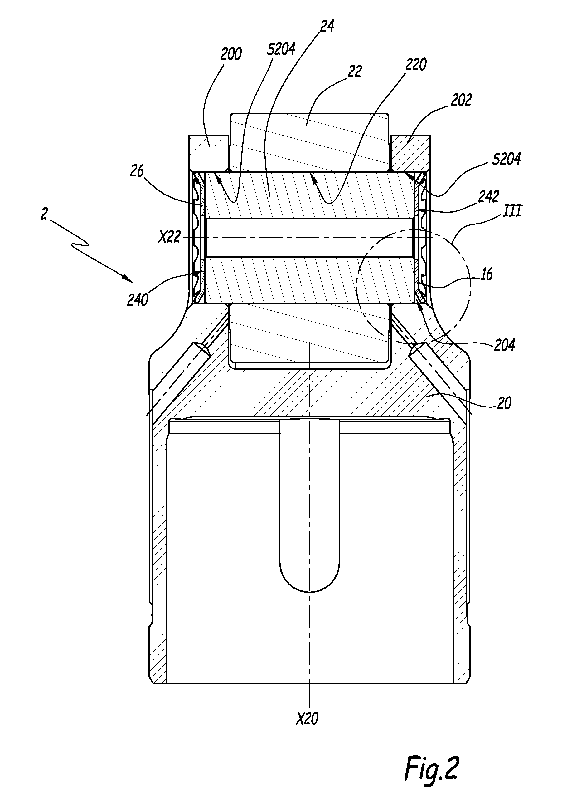
[0021]A cam follower unit 2 is represented on FIGS. 1 to 3. Cam follower unit 2 comprises a tappet 20, adapted to move in translational motion along a longitudinal axis X20 in a non-represented housing. Cam follower unit 2 also includes a roller 22, adapted to cooperate with a non-shown cam, for example in a valve control system or a fuel pump for an internal combustion engine. Roller 22 is rotatably mounted on a cylindrical pin 24, which is inserted in a central bore 220 of roller 22. Roller 22 is adapted to rotate around an axis X22 which is generally perpendicular to axis X20.

[0022]Tappet 20 comprises two lateral ears 200 and 202, which extend parallely to axis X20 and perpendicularly to axis X22. Each ear 200 and 202 comprises a circular hole 204 in which pin 24 is inserted.

[0023]In order to retain pin 24 in ears 200 and 202 along axis X22, which corresponds to the longitudinal direction of pin 24, cam follower unit 2 comprises elastic spring retainers 26, which are mounted agai...


PUM


Abstract

A cam follower unit comprising a tappet, a roller adapted to cooperate with a cam, the roller being mounted rotatably on a pin which is mounted in holes provided on two lateral ears of the tappet, the pin being retained in the tappet, in the longitudinal direction of the pin, by elastic spring retainers mounted against the ends of the pin, inside the holes of the lateral ears. The elastic spring retainers comprise a central portion adapted to be in contact with ends of the pin, the central portion defining a plane perpendicular to the central axis of the pin, and a peripheral portion adapted to exert a radial elastic force against an internal wall of the circular holes. The peripheral portion extends outwardly from the central portion and away from the pin along directions inclined with respect to the plane defined by the central portion.

Description

CROSS REFERENCE TO RELATED APPLICATIONS[0001]This is a Non-Provisional Patent Application, filed under the Paris Convention, claims the benefit of European Patent (EP) Application Number 14305902.0 filed on 13 Jun. 2014 (13.06.2014), which is incorporated herein by reference in its entirety.TECHNICAL FIELD[0002]The invention relates to a cam follower unit.BACKGROUND[0003]Cam follower units comprise a tappet and a roller adapted to cooperate with a cam, the roller being mounted rotatably on a pin which is mounted in holes provided in lateral ears of the tappet.[0004]It is known to retain the pin in the tappet in the longitudinal direction of the pin with elastic rings or circlips which are mounted in grooves provided on the internal wall of the holes of the lateral ears. Such grooves are difficult to obtain by turning and therefore imply a high cost.[0005]It is also known to retain the pin inside the tappet by caulking. This technique requires performing deformations on the ends of t...

Claims


Application Information

Patent Timeline
IPC IPC(8): F01L1/14F16H53/06F01L1/46
CPCF01L1/14Y10T74/2107F16H53/06F01L1/46F02M59/102F01L2305/02
Inventor BERRUET, NICOLASCHAMPALOU, FRANCOISHAUVESPRE, BENO TVIAULT, SAMUEL
Owner AB SKF
Learn More