
Adhesive mountable stack of removable layers

a technology of adhesive mount and lens layer, applied in the direction of film/foil adhesive, eye treatment, transportation and packaging, etc., can solve the problems of reducing the visibility through the eye protector to unacceptable or undesirable levels, reducing the multilayer tear off system to sub-optimal or even detrimental, and reducing visual acuity

Active Publication Date: 2015-12-17
RACING OPTICS
View PDF5 Cites 23 Cited by
  • Summary
  • Abstract
  • Description
  • Claims
  • Application Information

AI Technical Summary

Benefits of technology

The present patent describes eye protectors and methods for protecting them without reducing visual acuity. The eye protector has a center portion that matches the wearer's center of gaze and includes a lens that protects the wearer from projectiles. The lens has a refractive index that matches the refractive index of the eye protector. The eye protector also has an optically clear stack that includes one or more removable layers with a refractive index that matches the lens refractive index. The stack is attached to the lens using a dry mount adhesive layer that forms a continuous and uninterrupted adhesive surface over at least the center portion of the eye protector. The refractive indices of the lens, the dry mount adhesive layer, and each removable layer match within about 0.2. This eye protector design provides effective protection against projectiles while maintaining good visual acuity.

Problems solved by technology

One issue that can arise with multilayer tear off systems relates to the propensity of dirt to accumulate between the lowest layer of the multilayer tear off system and the transparent lens of the eye protector.
This accumulation of dirt can reduce visibility through the eye protector to unacceptable or undesirable levels, thereby rendering the multilayer tear off system sub-optimal or even detrimental.
Additionally, air disposed between the lowest layer of the system and the lens of the eye protector can result in undesirable reflections caused by a mismatch in the indices of refraction between lens, the system, and the air disposed therebetween.
These reflections can reduce contrast and light transmission and limit the amount of light that can pass through the system and eye protector, thereby reducing the wearer's visual acuity through the eye protector.
Moreover, the pins used to secure the transparent lens of the eye protector can reduce the impact resistance of the eye protector.
These holes can create points of weakness that reduce the structural integrity of the eye protector, thereby limiting the ability of the eye protector to shield against projectiles or other objects.
Further, pins can limit the system's ability to be applied to eye protectors of varying shape, design, or style.
Thus, a system designed to match one eye protector may be unusable for a different eye protector.

Method used


Image

  • Adhesive mountable stack of removable layers
  • Adhesive mountable stack of removable layers
  • Adhesive mountable stack of removable layers

Examples


Embodiment Construction

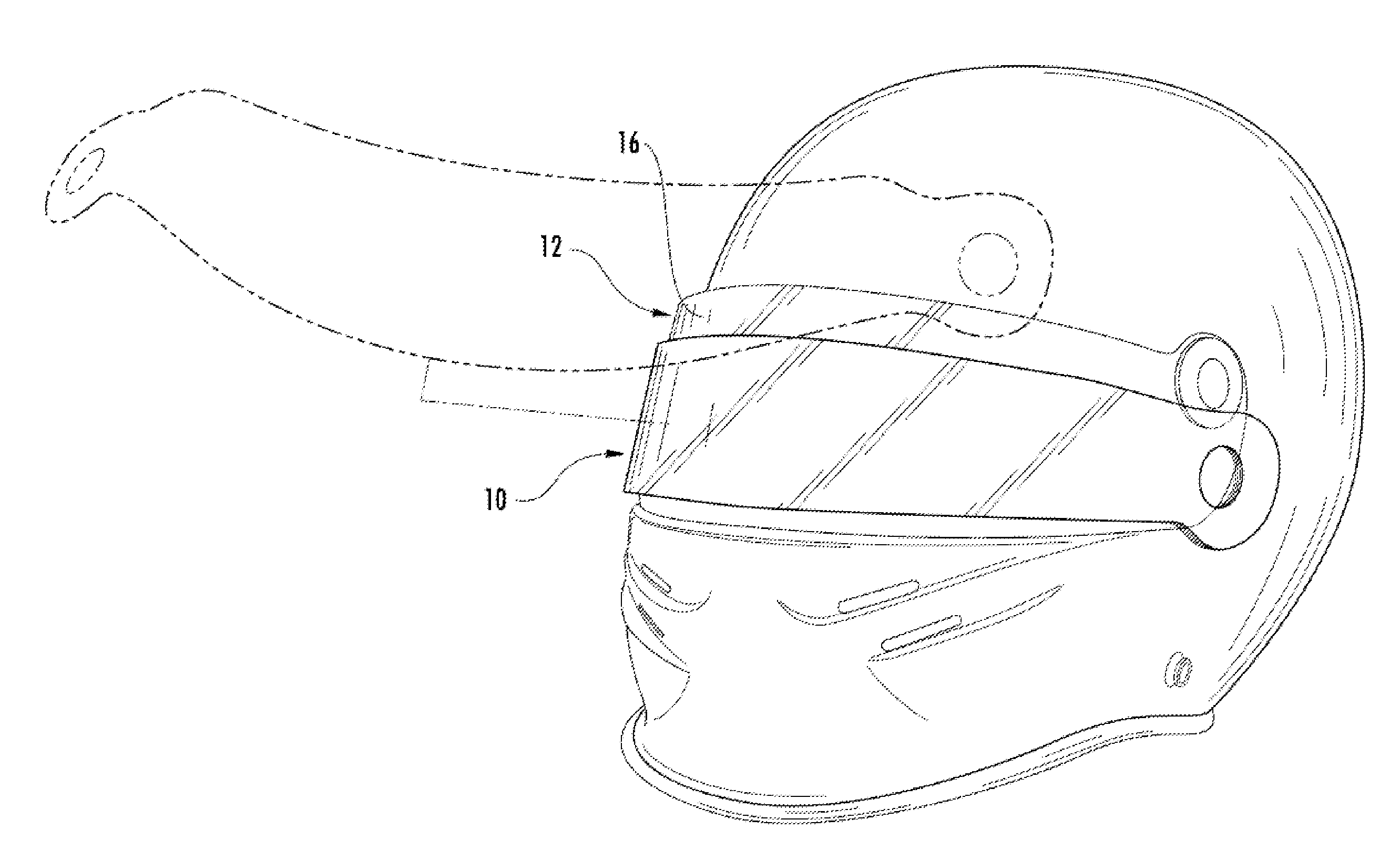
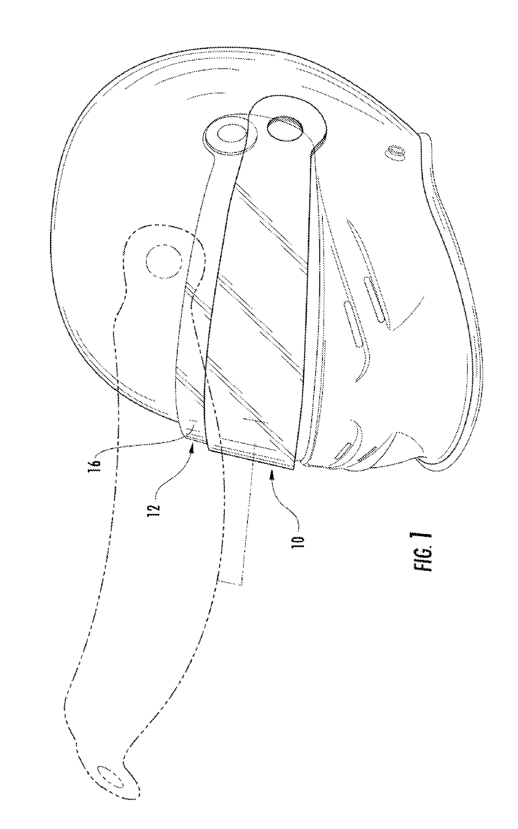
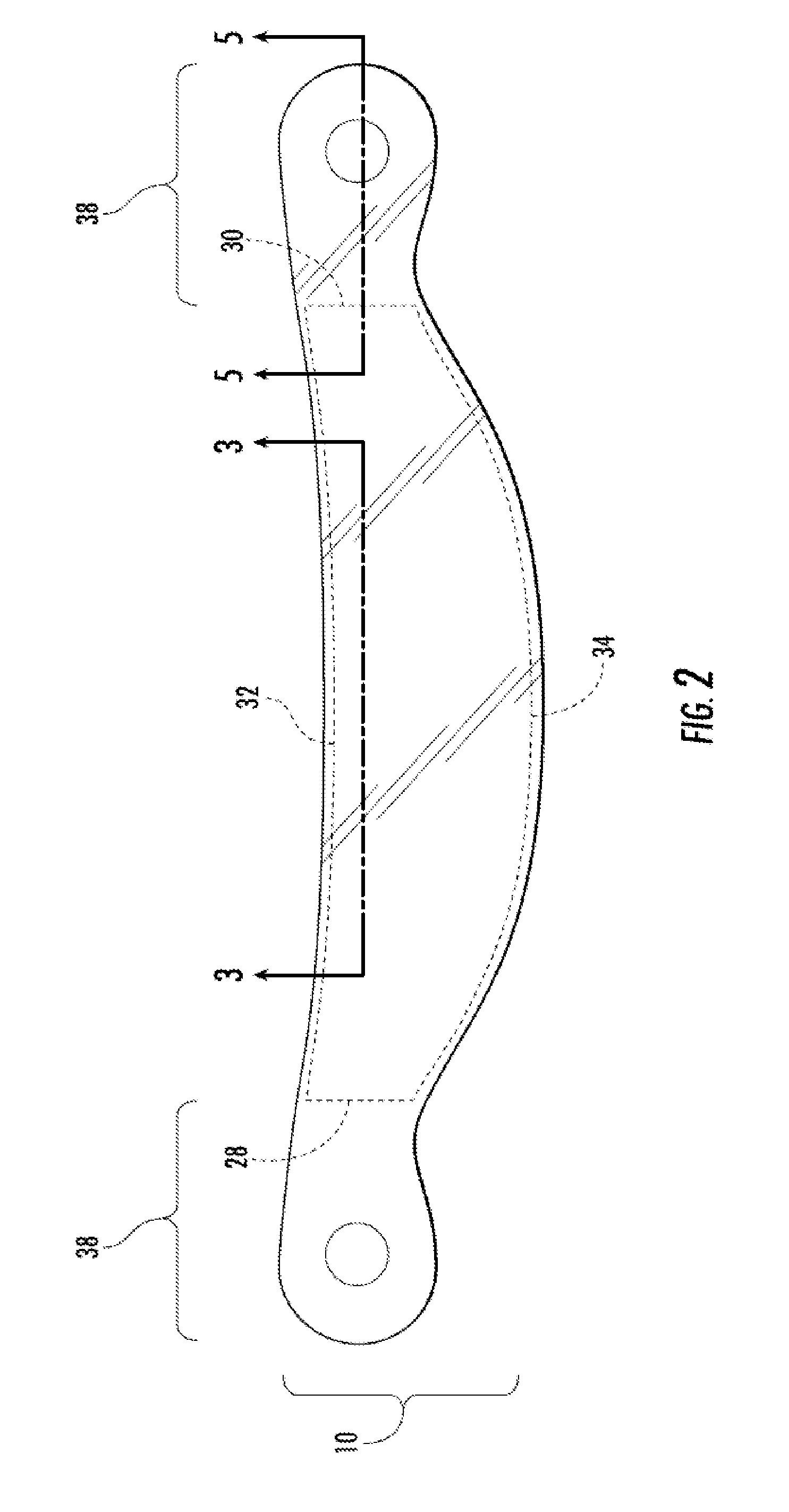
[0018]The present disclosure describes stacks mountable to an eye protector with an adhesive. As used throughout this specification, the term “stack” refers to a collection of one or more optically clear and / or transparent lens(es), film(s), or other layer(s) that can be attached and / or laminated together. As used herein, the phrase “optically clear” refers to a material having no perceptible visible distortion or scatter. An optically clear material may be transparent and / or colorless, but in some circumstances, a material that has a hue, shade, or a tint, for example, can be considered “optically clear” consistent with the meaning of the phrase as used herein. As used throughout this application, “eye protector” refers to optically clear objects designed to provide protection to the eyes and / or face of a wearer. “Eye protector” can refer to eye shields, face shields, lenses, glasses, masks, goggles, visors, windows, or the like. Moreover, where a particular eye protector is refere...


PUM

PropertyMeasurementUnit
Adhesivityaaaaaaaaaa
Refractive indexaaaaaaaaaa
Peel strengthaaaaaaaaaa

Abstract

An eye protector includes a lens configured to protect the wearer from projectiles, and an optically clear stack attached to the lens. The stack can have one or more removable layers. The eye protector also includes an optically clear dry mount adhesive layer attaching the stack to the lens. The dry mount adhesive may be self-wetting to attach the stack to the lens so that air between the stack and the lens can be removed after the stack is attached and / or adhered to the lens, for example, by applying pressure across the surface of the stack. The refractive indices of the lens, the dry mount adhesive, and each removable layer are matched to within about 0.2.

Description

RELATED APPLICATIONS[0001]Not ApplicableTECHNICAL FIELD[0002]The present disclosure generally relates to an adhesive mountable stack of lens layers. More specifically, the present disclosure relates to a stack of removable lens layers configured for dry mounting to optically clear eye protective surfaces.BACKGROUND[0003]Multilayer tear off systems can be attached to eye protective surfaces, such as goggles or face shields, with pins. In this way, pins are attached outside of the primary viewing area of the eye protector, for example, to left and right sides of the eye protector surface. To attach the system to an eye protector, the system is wrapped tightly around the optically clear lens of the eye protector by pulling the system over the pins. One example of a multilayer tear off system attached to pins of an eye protector is disclosed in U.S. Pat. No. 6,388,813, issued to the assignee of the instant application.[0004]One issue that can arise with multilayer tear off systems relat...

Claims


Application Information

Patent Timeline
IPC IPC(8): A61F9/02
CPCA42B3/26Y10T428/14C09J7/30B32B7/06B32B7/12C09J133/12B32B7/023A61F9/045B32B27/08B32B27/365B32B2250/244B32B2307/412B32B2307/418B32B2367/00A61F9/025
Inventor WILSON, BART E.
Owner RACING OPTICS
Learn More