
Intermesh engagement device

a technology of engagement device and intermingle, which is applied in the direction of mechanical actuated clutches, interengaging clutches, transportation and packaging, etc., can solve the problem of insufficient reduction of collision noise, and achieve the effect of reducing collision nois

Active Publication Date: 2015-12-10
TOYOTA JIDOSHA KK
View PDF1 Cites 15 Cited by
  • Summary
  • Abstract
  • Description
  • Claims
  • Application Information

AI Technical Summary

Benefits of technology

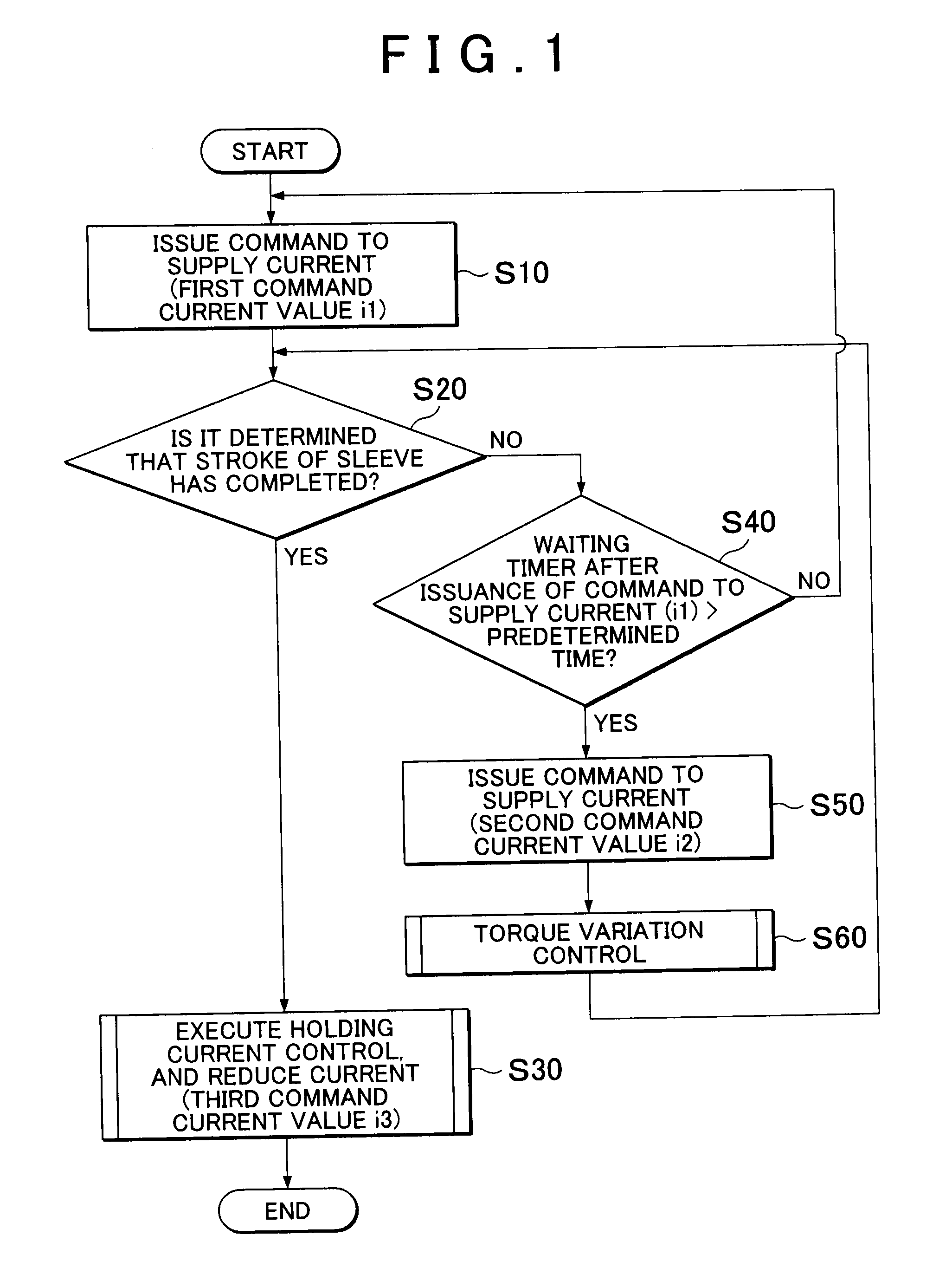
The invention is an intermesh engagement device that reduces noise caused by collisions between moving parts and stoppers. The device has an electronic control unit that first controls the actuator to achieve a thrust when the engagement mechanism is engaged. If there is a halfway stop in the engagement process, the control unit increases the actuator thrust to a larger value. This prevents the occurrence of noise caused by the collision between the moving parts. The device is advantageous in reducing noise and improving the overall performance of the engagement mechanism.

Problems solved by technology

With such a configuration, if the thrust is controlled on the basis of the stroke amount of the sleeve, there is a possibility that collision noise is not sufficiently reduced because the speed of the moving member is not accurately controlled.

Method used


Image

  • Intermesh engagement device
  • Intermesh engagement device
  • Intermesh engagement device

Examples


first embodiment

[0032]As shown in FIG. 2, a vehicle driving system 100 includes an engine 1, a first planetary gear train 10, a second planetary gear train 20, a first rotating machine MG1, a second rotating machine MG2, and the intermesh engagement device 60. The vehicle driving system 100 is a driving system for a hybrid vehicle, and includes the first rotating machine MG1 and the second rotating machine MG2 in addition to the engine 1 as a power source.

[0033]The engine 1 converts the combustion energy of fuel into rotating motion and then outputs the rotating motion. The rotary shaft of the engine 1 is connected to an input shaft 2. The input shaft 2 is connected to a first carrier 14 of the first planetary gear train 10. The first planetary gear train 10 is of a single pinion type, and includes a first sun gear 11, first pinion gears 12, a first ring gear 13 and the first carrier 14. The first carrier 14 is connected to the input shaft 2, and integrally rotates with the input shaft 2. The firs...

second embodiment

[0099]The first carrier 14 is connected to the second ring gear 23, and integrally rotates with the second ring gear 23. The first ring gear 13 is connected to the second carrier 24, and integrally rotates with the second carrier 24. As in the case of the vehicle driving system 101 the second rotating machine MG2 is connected to the output shaft 33 via the transmission unit 34.

[0100]The intermesh engagement device 60 functions as a brake device that restricts the rotation of the second sun gear 21. When the intermesh engagement device 60 is in the released state, the ECU 50 causes the first rotating machine MG1 to function as a reaction receiver against engine torque. The first rotating machine MG1 causes the engine torque to be output from the first ring gear 13 to the output shaft 33 by outputting reaction torque.

[0101]When the intermesh engagement device 60 is in the engaged state, the rotation of the second sun gear 21 is restricted. Thus, the second sun gear 21 functions as a ...


PUM


Abstract

An intermesh engagement device includes an intermesh engagement mechanism, a moving member, an actuator configured to apply a thrust to a moving member in an engaging direction, a transmission spring configured to transmit the thrust of the actuator from the moving member to a sleeve, a return spring, a stopper, and an electronic control unit configured to control the actuator. The electronic control unit is configured to execute first control for setting the thrust of the actuator to a thrust in a first region, and, when a halfway stopped state has occurred through the first control, execute second control for setting a thrust larger than the thrust in the first control. The first region is a range in which the thrust is larger than an urging force of the return spring and is smaller than the sum of the urging force of the return spring and a maximum urging force of the transmission spring.

Description

INCORPORATION BY REFERENCE[0001]The disclosure of Japanese Patent Application No. 2014-118969 filed on Jun. 9, 2014 including the specification, drawings and abstract is incorporated herein by reference in its entirety.BACKGROUND OF THE INVENTION[0002]1. Field of the Invention[0003]The invention relates to an intermesh engagement device.[0004]2. Description of Related Art[0005]There is an existing intermesh engagement device. For example, Japanese Patent Application Publication No. 2010-25279 (JP 2010-25279 A) describes a controller for an electromagnetic clutch. The controller includes first setting means and second setting means. At the time when a pair of clutch elements are changed from a non-engaged state to an engaged state, the first setting means sets a first drive current as an initial drive current for an electromagnetic actuator such that a plunger is accelerated in a direction as a result of application of an urging force to the plunger and then the plunger is decelerate...

Claims


Application Information

Patent Timeline
Patent Type & Authority Applications(United States)
IPC IPC(8): F16D48/06F16D11/14
CPCF16D48/064F16D11/14F16D2011/004F16D2500/70631F16D2500/10412F16D2500/50239F16D2500/1022F16H2061/047B60K6/445F16D27/118B60K2006/381F16D2011/008F16D2500/3026F16D2500/70418F16D2500/7044B60K6/38B60K6/387Y02T10/62F16H61/02F16D11/10F16D2500/10462
Inventor EBUCHI, HIROAKIFUNAHASHI, MAKOTOIWASE, YUJIKATO, SHOTARONAGAI, HIDEKAZUHASHIMOTO, HIROTO
Owner TOYOTA JIDOSHA KK
Learn More