
Adaptation of a hydraulic motor

Active Publication Date: 2015-12-10
DANFOSS POWER SOLUTIONS GMBH & CO
View PDF4 Cites 5 Cited by
  • Summary
  • Abstract
  • Description
  • Claims
  • Application Information

AI Technical Summary

Benefits of technology

The invention is an axial piston machine that can be used in a hydraulic drive. The design features multiple benefits, including a compact and simple design, reduced costs, and the use of a common "dry" case for the machine. This allows for the lubricant or leakage fluid to flow out of the machine and into the hydraulic gearing case, eliminating the need for dedicated shaft or motor seals. Additionally, the design allows for the use of smaller bearings, further reducing costs. Overall, the invention provides a more efficient and cost-effective solution for hydraulic drives.

Problems solved by technology

As drive assembly parts rotate in the liquid-filled case, energy losses occur, which are referred to as splashing losses.

Method used


Image

  • Adaptation of a hydraulic motor
  • Adaptation of a hydraulic motor
  • Adaptation of a hydraulic motor

Examples


Embodiment Construction

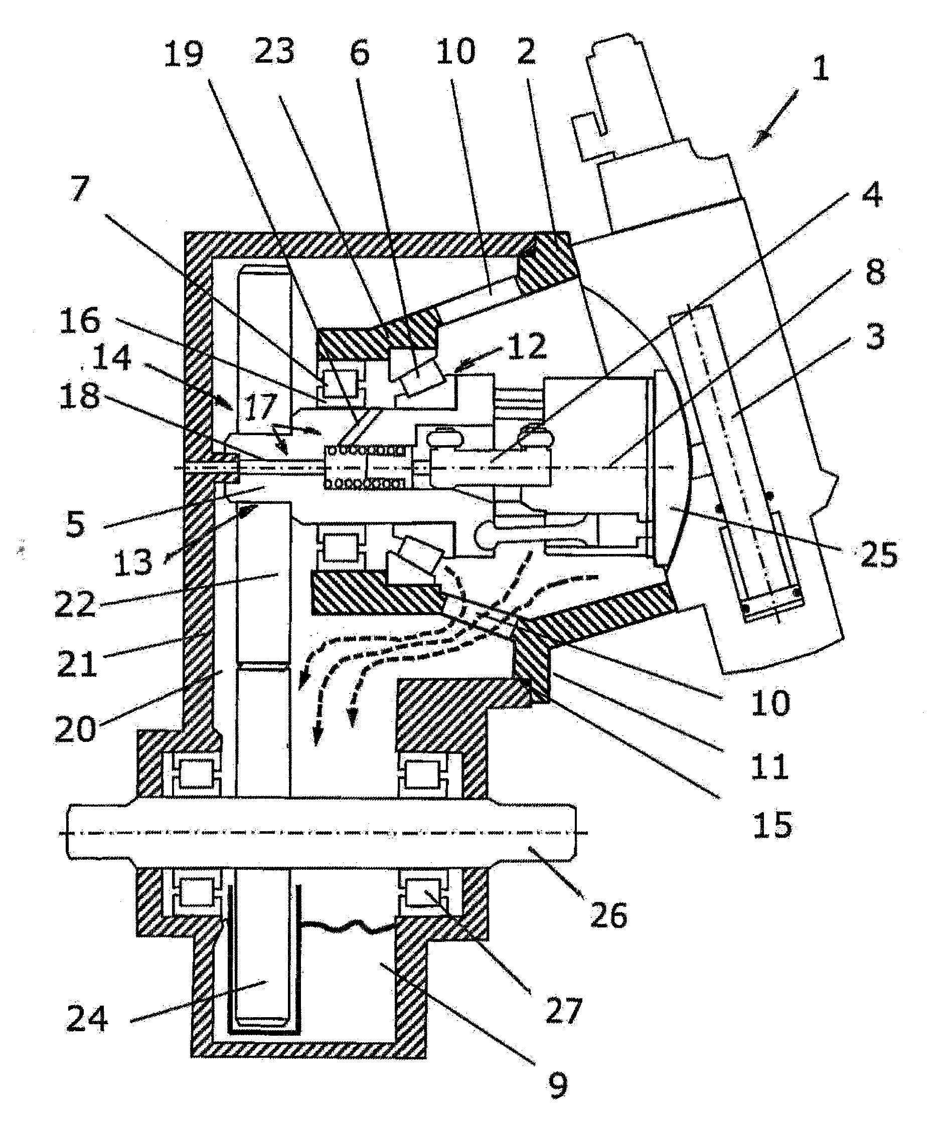
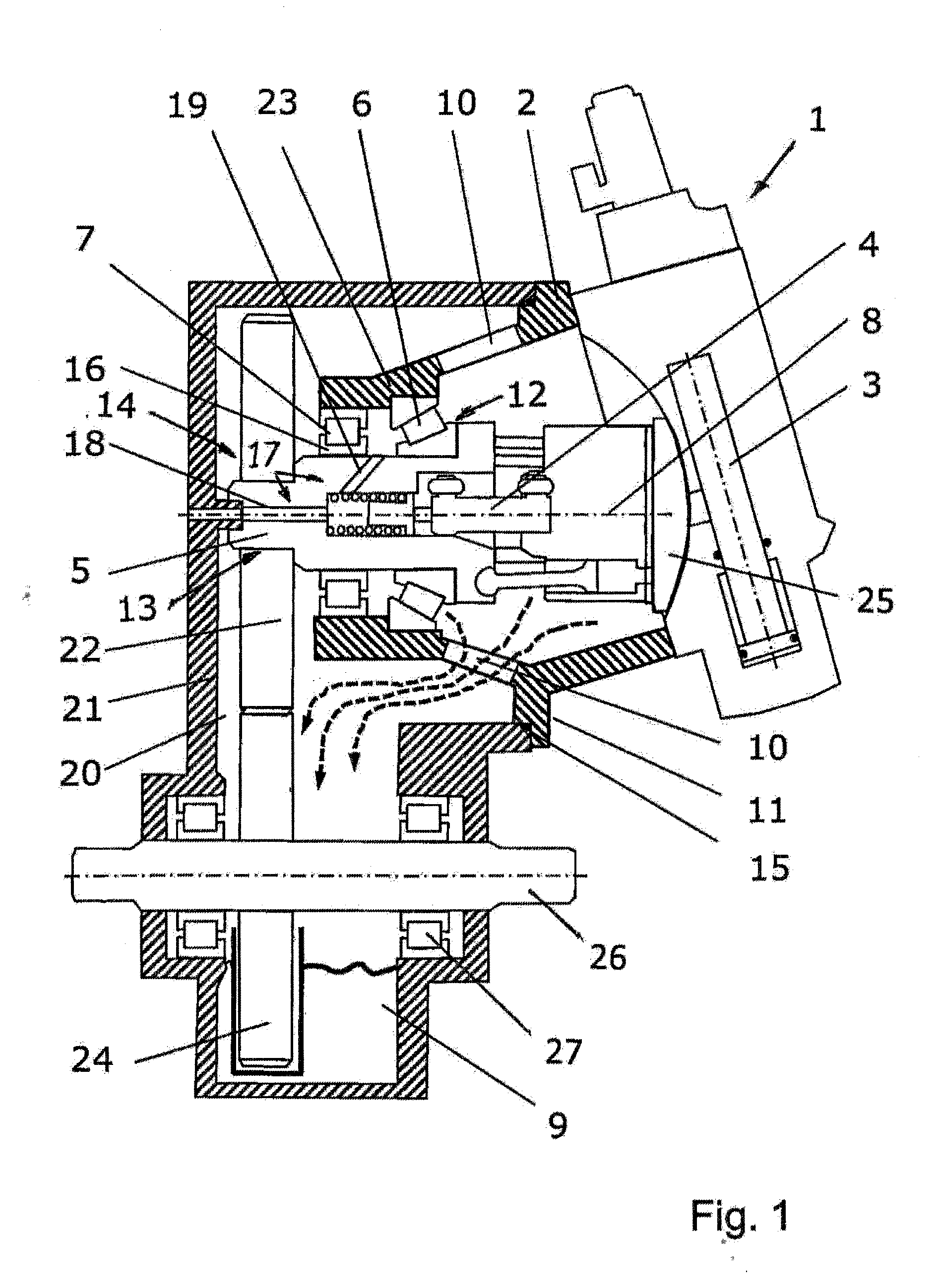
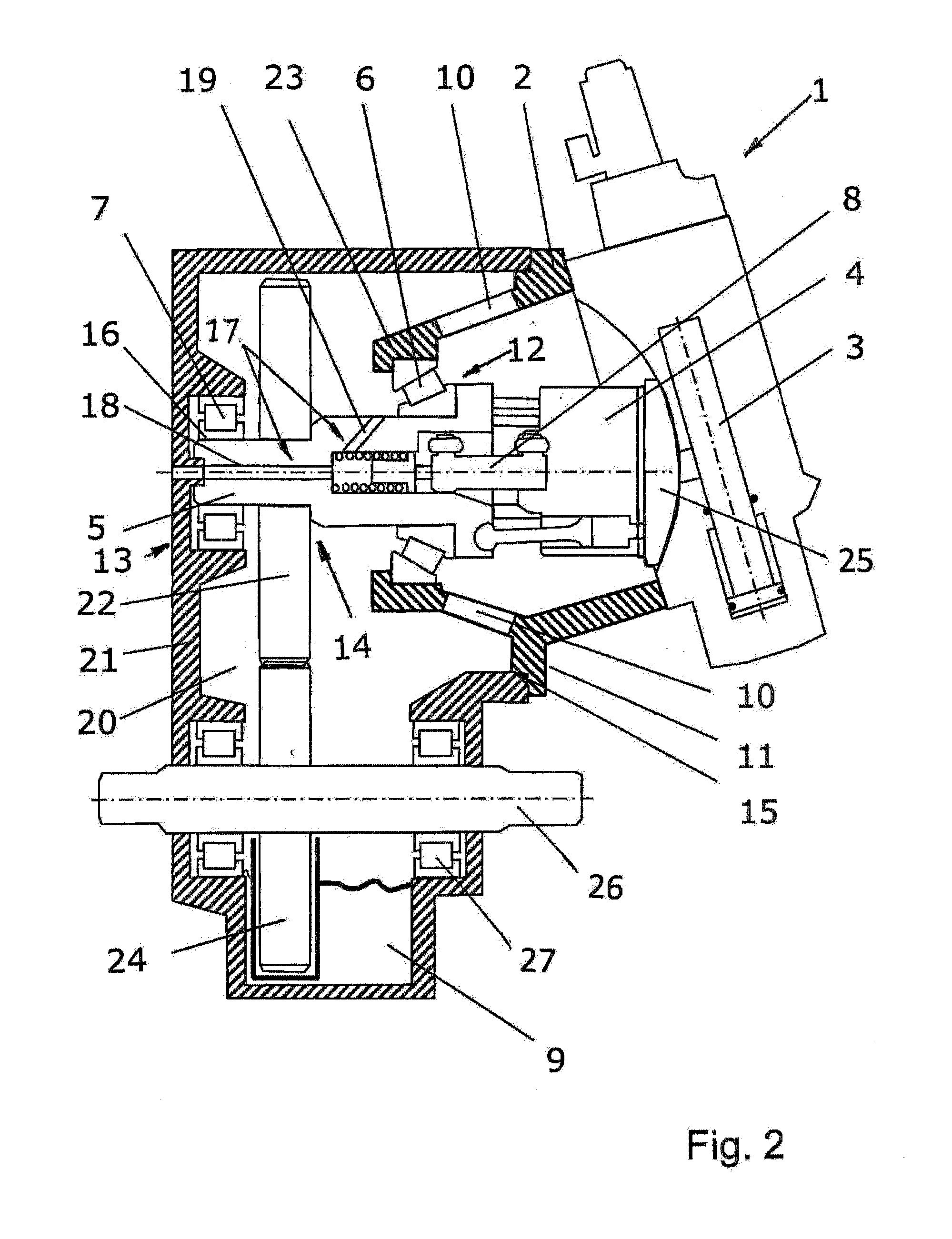
[0023]FIG. 1 illustrates a cross section through a hydraulic axial piston machine 1 of dry case type of construction according to the invention in a first embodiment. The axial piston machine 1 is in this case shown, by way of example, as an adjustable motor or pump of oblique axis type of construction, which has, in a case 2, a drive assembly 4, the valve segment 25 of which is engaged on by an adjustment device 3. The basic design and mode of operation of an axial piston machine 1 of said type are familiar to a person skilled in the art, such that no further explanations will be given in this regard.

[0024]The drive assembly 4 has a drive shaft 5 which is mounted, in a first bearing region 12 and a second bearing region 13, in a respective bearing 6, 7. The bearing 6 in the first bearing region 12 is in this case in the form of a tapered-roller bearing, whereas the bearing 7 in the second bearing region 13 is shown as a rolling bearing with an inner ring 16. The longitudinal axis o...


PUM


Abstract

The invention relates to a hydraulic axial piston machine (1) of dry case type of construction, whose case (2) is provided for connection to a gearing case (21) so as to form a fluid-tight overall case. The case (2) has openings (10) which permit the passage of leakage hydraulic fluid or of lubricant into the gearing case (21). By means of this design, splashing losses of the axial piston machine (1) are eliminated, and the leakage hydraulic fluid or the lubricant serve for the lubrication both of the axial piston machine (1) and of the gearing (20).

Description

BACKGROUND OF THE INVENTION[0001]The invention relates to an adjustable hydraulic axial piston machine of dry case type of construction, as per claim 1.[0002]A hydraulic axial piston machine of said type is known for example from DE 44 14 509 C1. It is stated in said document that, in the case of conventional hydraulic machines, the case is constantly filled with liquid owing to inevitable pressure fluid leakage. As drive assembly parts rotate in the liquid-filled case, energy losses occur, which are referred to as splashing losses. To reduce splashing losses, it is advantageous, in particular in the case of operation at high rotational speeds, for the liquid to be removed from the machine case in order that the drive assembly rotates in a case that has been emptied of oil. For the removal of liquid from the case, various methods have been proposed which are based on the extraction of the leakage liquid by suction. The type of construction of hydraulic axial piston machines realized...

Claims


Application Information

Patent Timeline
IPC IPC(8): F01B3/00
CPCF01B3/0005F01B3/0023F01B3/0044F04B1/24F04B23/028F04B53/18
Inventor GOELLNER, WILHELM
Owner DANFOSS POWER SOLUTIONS GMBH & CO
Learn More