
Solar panel curtain device

a solar panel and curtain technology, applied in the safety of solar heat collectors, power supply testing, lighting and heating apparatus, etc., can solve the problems of reducing the efficiency of solar panel power generation, reducing the amount of concentrated light, and reducing the efficiency of concentrated light, so as to protect solar panels from weather phenomena more efficiently and maximize the effect of power generation

Inactive Publication Date: 2015-12-03
JUAN ENERGY
View PDF4 Cites 10 Cited by
  • Summary
  • Abstract
  • Description
  • Claims
  • Application Information

AI Technical Summary

Benefits of technology

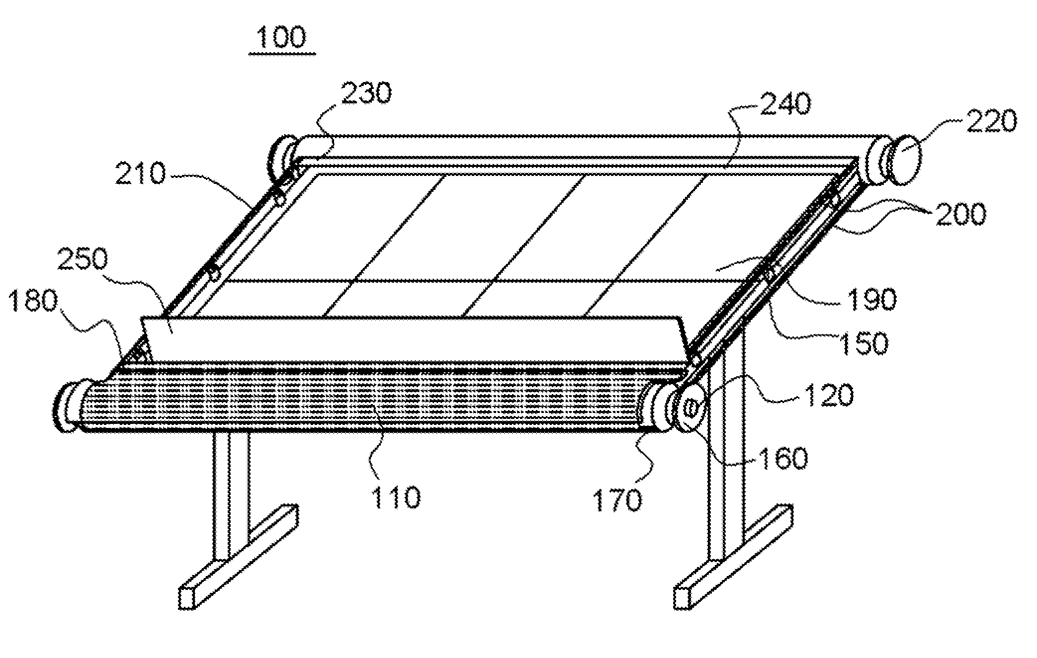
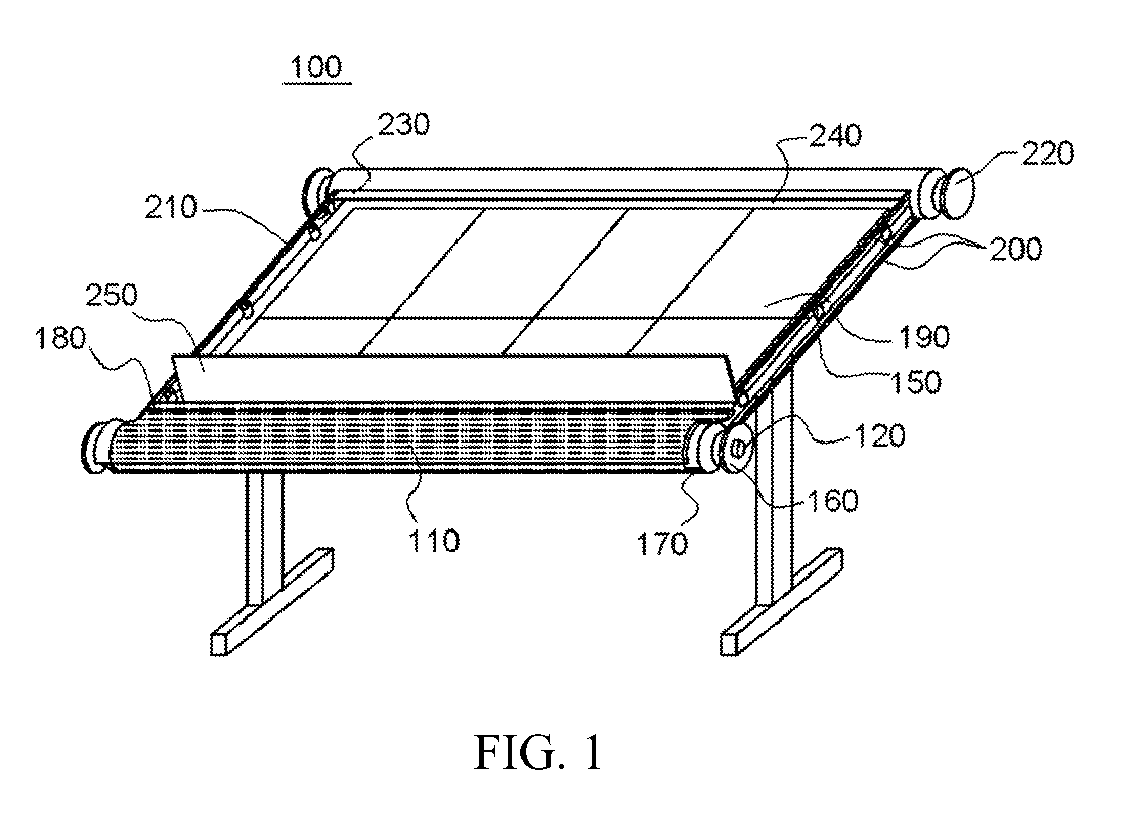
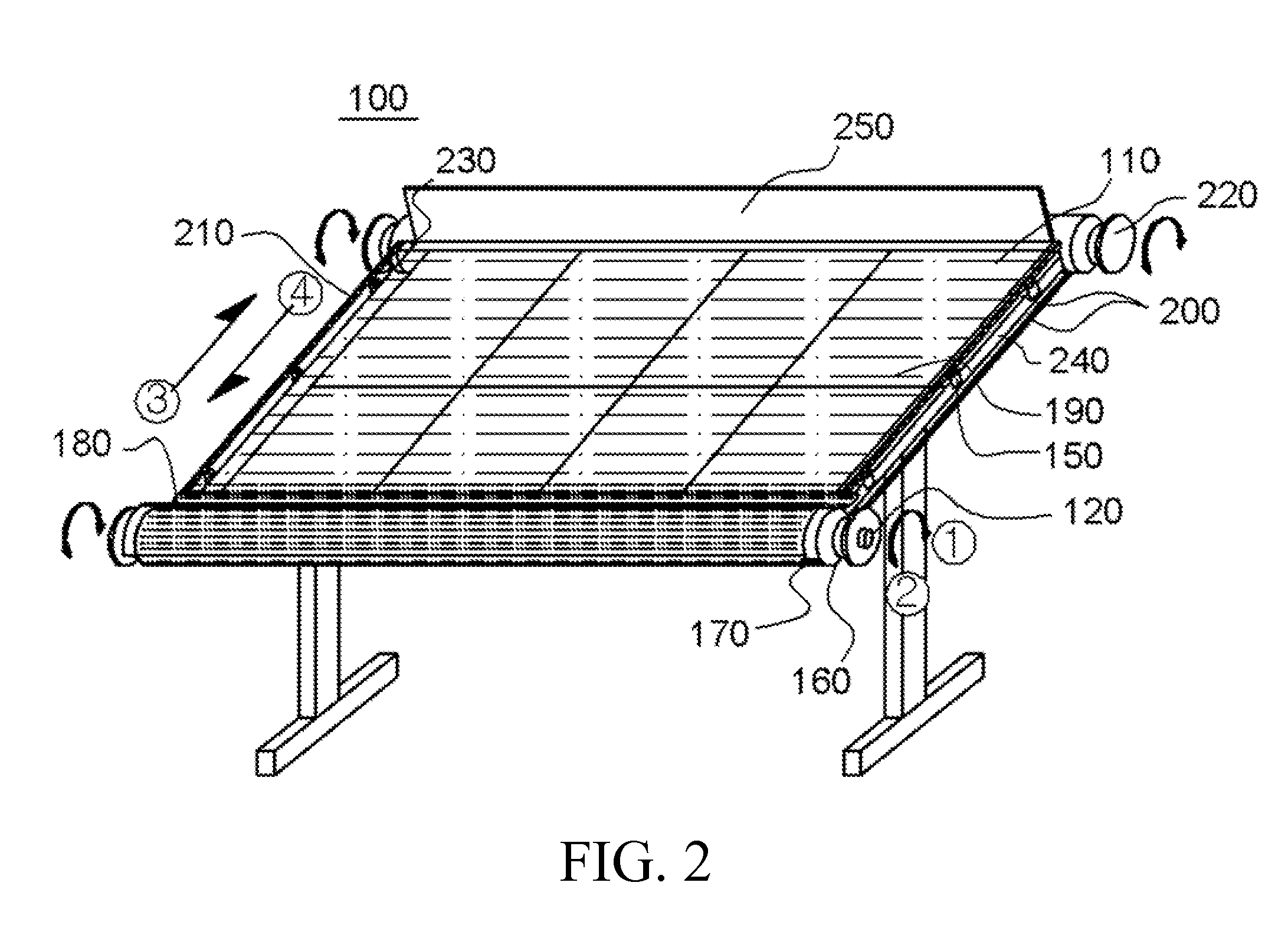
The present invention is about a solar panel curtain device that can keep the solar panels clean and efficient by using a panel curtain that covers the panels and automatically removes snow or other foreign substances. This device can communicate with a weather information providing server to automatically adjust to the weather, without requiring human intervention. By measuring the pressure caused by accumulated snow on the panel curtain, it can also protect the solar panel from weather phenomena more efficiently. The technical effects of this invention include maximizing the efficiency of power generation and ensuring a long-term solar panel lifespan.

Problems solved by technology

However, since solar cells for concentrating sunlight, the solar module and the solar array are installed in the outside and exposed to external environment, dust scattering, bird feces, sand dust, and other contaminating substances are attached to them, and thereby reduce the amount of concentrated light decreasing the efficiency.
Especially in the winter season, snow covers the solar cells, the photovoltaic module and the solar array, as foreign substances are attached, reducing the amount of concentrated light and decreasing the efficiency.
Furthermore, the efficiency of power generation decreases because the temperature increases due to a long period of exposure to sunlight and thus electromotive force reduces.
The cleaning device using a brush has disadvantages that a special brush appropriate for the maintenance system of solar-light power generation should be manufactured and it does not provide a way of cooling when the solar array is overheated.
The cleaning device using water flow via gravity has a disadvantage that it is not that effective in eliminating contaminating substances or snow.
This cleaning device, however, requires high installation and operation cost in maintaining high pressure required for cooling and cleaning because the nozzle part ejecting water is generally fixed and not rotatable, requiring many nozzles in case the area of solar array is large.
Moreover, in case water is ejected randomly with fixed nozzles, a large amount of water may be wasted because it is difficult to eject water to a desired area.
In addition, because the piping for adjusting ejection angle of the nozzles casts shadows on the solar array, the efficiency of the power generation decreases or a larger area is required due to a longer distance between the solar arrays.
In particular, in case of solar arrays formed in a large scale, because the numbers of nozzles for cooling and cleaning increase accordingly, there exists a difficult task that a sufficient efficiency for snow-removing, cooling, and cleaning should be achieved by avoiding the shadows, ejecting water to photovoltaic modules with an appropriate pressure, and effectively using a limited water resource.
Also, in the winter season, there is a problem that the power generation efficiency decreases due to a rapid reduction of power generation when snow covers the upper surface of the solar array.

Method used


Image

  • Solar panel curtain device
  • Solar panel curtain device
  • Solar panel curtain device

Examples


Embodiment Construction

Technical Problem

[0014]The present invention has been developed to improve the conventional art, and an object of the present invention is to provide a solar panel curtain device that maximizes the life of the panel and the power generation efficiency by covering the solar panel automatically and protecting the solar panel from foreign substances and weather phenomena such as snow and sandy dust.

TECHNICAL SOLUTION

[0015]In order to resolve the problem of the conventional art, a solar panel curtain device according to an embodiment of the present invention comprises: a solar panel provided tilting at a predetermined angle relative to the ground surface, corresponding to the angle of incidence of sunlight; a first roll housing provided at the lower edge of the solar panel, having formed therein a first rotational shaft and an inner accommodating space, and having formed at one side thereof a slot adapted such that a panel curtain can withdraw into the inner accommodating space or advan...


PUM


Abstract

According to one embodiment of the present invention, a solar panel curtain device comprises: a solar panel provided tilting at a predetermined angle relative to the ground surface, corresponding to the angle of incidence of sunlight; a first roll housing provided at the lower edge of the solar panel, having formed therein a first rotational shaft and a solar panel curtain accommodating space, and having formed on one side thereof a slot adapted such that the solar panel curtain can withdraw into the inner accommodating space or advance out of the inner accommodating space; a second roll housing provided at the upper edge of the solar panel, and having formed therein a second rotational shaft; a first rail and a second rail respectively touching the two ends of the first rotational shaft and the two ends of the second rotational shaft, and performing rotational motions on two sides of the solar panel; and a panel curtain of which the ends on both sides respectively touch the first rail and the second rail, and which operates so as either to be stowed in the inner accommodating space of the first roll housing or to cover the solar panel, in accordance with the rotational motions of the first rail and the second rail.

Description

TECHNICAL FIELD[0001]The present invention relates to a solar panel curtain device and, more particularly, to a solar panel curtain device that can maximize the life of the panel and the power generation efficiency by covering the solar panel automatically and protecting the solar panel from foreign substances and weather phenomena such as snow and sandy dust.Background Art[0002]Methods of using solar energy are generally divided into two methods, a method of using solar heat and a method of using solar light. The method of using solar heat utilizes water heated by sun for heating and power generation. The method of using solar light, so called solar-light power generation, generates electricity by using solar light and operates various machines and apparatuses with the electricity.[0003]The solar-light power generation generates electricity by utilizing photovoltaic effect which generates an electromotive force by electrons-holes with the light energy when sun light illuminates to ...

Claims


Application Information

Patent Timeline
Patent Type & Authority Applications(United States)
IPC IPC(8): H02S20/30H02S30/20G01R31/40H02S30/10H01L31/042
CPCH02S20/30H02S50/00H02S30/20H02S30/10Y02E10/40H02S40/12F24S40/10Y02E10/50H01L31/042
Inventor KIM, JAE IL
Owner JUAN ENERGY
Learn More