Turbine bucket assembly and turbine system

Inactive Publication Date: 2015-12-03
GENERAL ELECTRIC CO
View PDF8 Cites 9 Cited by
  • Summary
  • Abstract
  • Description
  • Claims
  • Application Information

AI Technical Summary

Benefits of technology

This patent is about a turbine bucket assembly that includes a multi-lobe joint with a root segment and tip segment. The tip segment is shorter than the root segment and is connected to the root segment with a thread. A turbine wheel is attached to the multi-lobe joint and has a geometry that matches that of the joint. The tip segment and root segment materials have lower heat resistance and higher thermal expansion than the tip segment material. This design allows for improved performance and durability of the turbine bucket assembly.

Problems solved by technology

The roots of at least some known buckets are coupled to the disk with dovetails that are inserted within corresponding dovetail slots formed in the rotor disk to form a bladed disk, or “blisk.” Because such turbine engines operate at relatively high temperatures and may be relatively large, the operating capacity of such an engine may be at least partially limited by the materials used in fabricating the buckets and / or the length of the airfoil portions of the buckets.

Method used


Image

  • Turbine bucket assembly and turbine system
  • Turbine bucket assembly and turbine system
  • Turbine bucket assembly and turbine system

Examples


Embodiment Construction

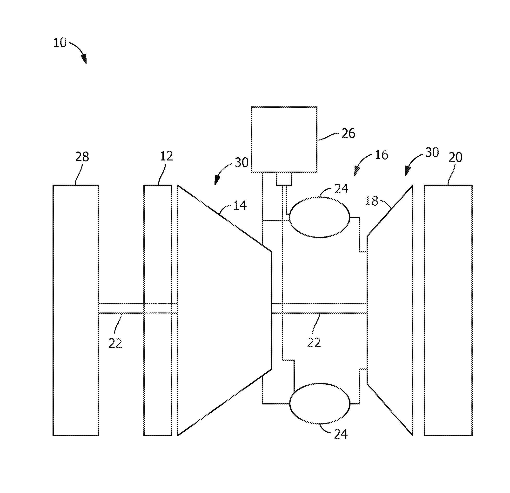
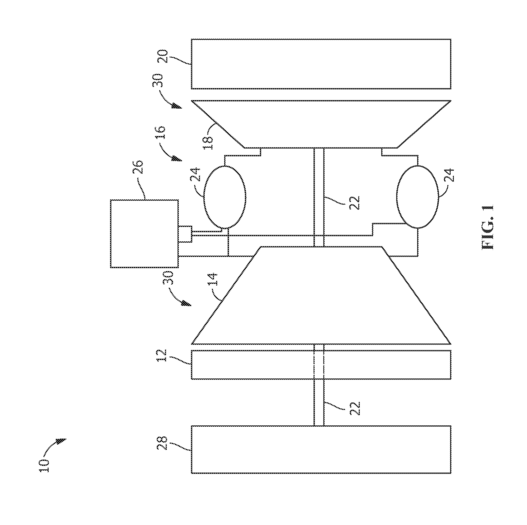
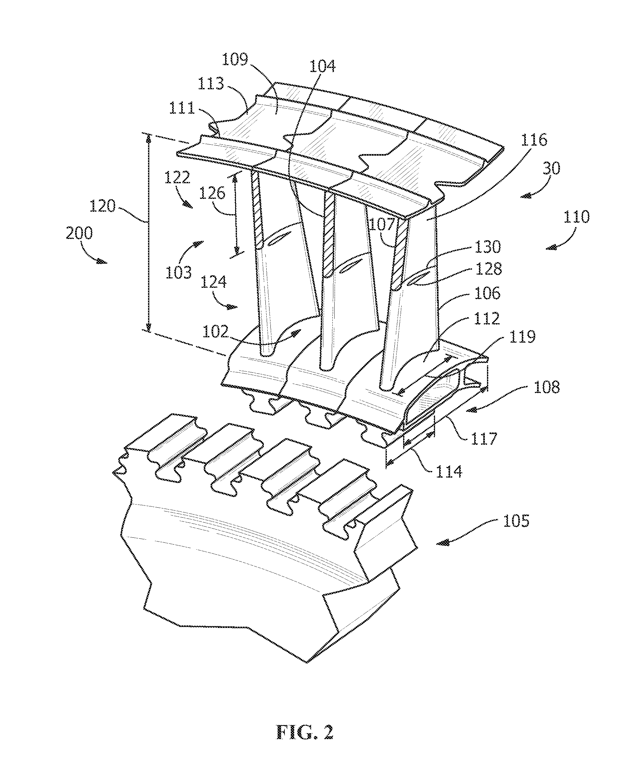
[0013]Provided is a turbine bucket assembly and a turbine system. In addition, methods of assembling and / or producing such turbine bucket assemblies and turbine systems are apparent from the disclosure. Embodiments of the present disclosure, for example, in comparison to similar concepts failing to include one or more of the features disclosed herein, use a lighter material in a tip segment of an airfoil in comparison to a root segment to reduce structural loading and / or permit control of a vibratory response (in comparison to a monolithic airfoil), use a denser material in a root segment of an airfoil to reduce risk of failure (in comparison to a monolithic airfoil), permit easier repair of damage (for example, by a tip-rub event, overheating, and / or any other damaging event) by permitting the tip segment to be repaired alone without requiring more expensive and more time-consuming removal and repair / replacement of the complete turbine bucket, reduce overall operating and maintenan...


PUM


Abstract

A turbine bucket assembly and turbine system are disclosed. The assembly includes a multi-lobe joint having an integral platform, the joint having a first axial length; a segmented airfoil having a root segment extending radially outward from the platform and a tip segment coupled to the root segment, the tip segment having a second axial length less than the first axial length; and a turbine wheel defining a receptacle with a geometry corresponding to the multi-lobe joint and being coupled to the multi-lobe joint. A tip segment material, a root segment material, and a turbine wheel material are selected, such that the turbine wheel material and the root segment material have a lower heat resistance and a higher thermal expansion than the tip segment material.

Description

FIELD OF THE INVENTION[0001]The present invention is directed to turbine components and turbine systems. More particularly, the present invention is directed to turbine bucket assemblies and turbine systems having one or more turbine bucket assemblies.BACKGROUND OF THE INVENTION[0002]At least some known gas turbine engines include a combustor, a compressor, and / or turbines that include a rotor disk that includes a plurality of rotor blades, or buckets, that extend radially outward therefrom. The plurality of rotating turbine blades or buckets channel high-temperature fluids, such as combustion gases or steam, through either a gas turbine engine or a steam turbine engine. The roots of at least some known buckets are coupled to the disk with dovetails that are inserted within corresponding dovetail slots formed in the rotor disk to form a bladed disk, or “blisk.” Because such turbine engines operate at relatively high temperatures and may be relatively large, the operating capacity of...

Claims


Application Information

Patent Timeline
IPC IPC(8): F01D5/22
CPCF01D5/225F01D5/10F01D5/147F01D5/282F05C2251/046C22C14/00C22C21/00F01D5/28F01D5/284F01D5/288F01D5/3007F05D2300/174F05D2300/175F05D2300/522F05D2300/5021F05D2300/176C22C19/055C22C19/07F05D2300/6033
Inventor DAVIDSON, DWIGHT ERICBALSONE, STEPHEN JOSEPHPOTTER, BRIAN DENVER
Owner GENERAL ELECTRIC CO
Why Eureka
Try Eureka