
Data center congestion management for non-tcp traffic

Active Publication Date: 2015-11-26
INTEL CORP
View PDF4 Cites 40 Cited by
  • Summary
  • Abstract
  • Description
  • Claims
  • Application Information

AI Technical Summary

Benefits of technology

The patent text discusses the problem of congestion in data centers and the impact it can have on network performance. The text describes various techniques for managing congestion, such as QCN and DCTCP, and their limitations. The technical effect of the invention is to provide a more efficient and effective solution for managing congestion in data centers, allowing for faster convergence times and better performance at high rates of data transfer.

Problems solved by technology

Performance of the network(s) within the data center can be impacted by congestion.
If applicable, the switches will also drop packets, which exacerbates the congestion problems since the dropped packets have to be resent for confirmed delivery protocols such as TCP.
Unfortunately, DCTCP is not relevant for non-TCP traffic like RDMA over Converged Ethernet (RoCE) or Fibre Chanel over Ethernet (FCoE).
Also, QCN has tentatively addressed its inherent weaknesses by a greater rate decrease factor at the reaction points, which in return led to throughput penalties and longer recovery times at the source nodes.
For these reasons, QCN is not performing well for 10 Gbps (and higher rates), and in any case, it is not performing as well as DCTCP.
In addition, since QCN is a Layer2 control protocol, it is limited within the Layer2 Ethernet cloud and it cannot extend beyond the IP subnet, as required for overlays / tunneled environments that carry an IP header while not including a TCP header.

Method used


Image

  • Data center congestion management for non-tcp traffic
  • Data center congestion management for non-tcp traffic
  • Data center congestion management for non-tcp traffic

Examples


Embodiment Construction

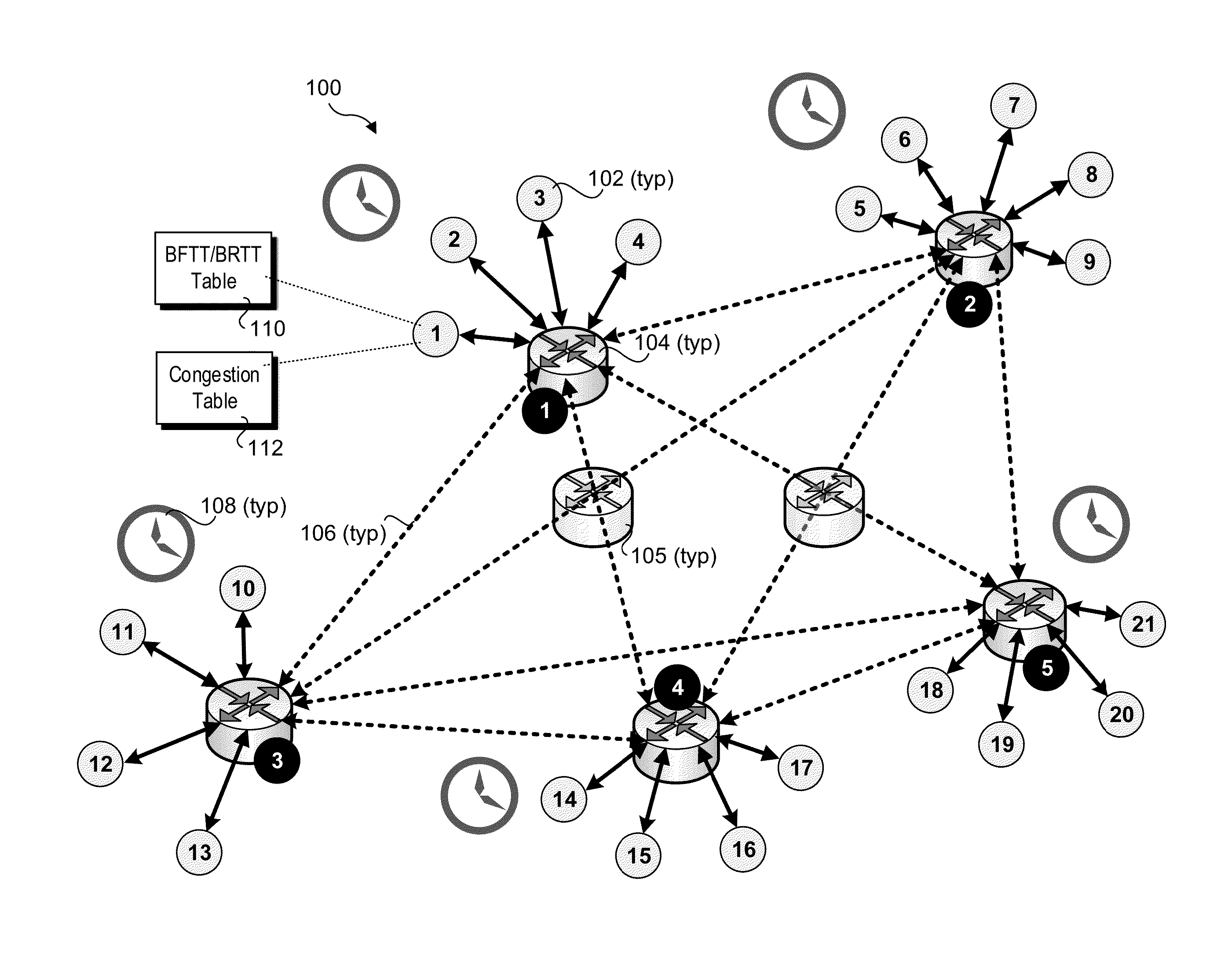
[0019]Embodiments of methods, apparatus and software for implementing enhanced data center congestion management for non-TCP traffic are described herein. In the following description, numerous specific details are set forth to provide a thorough understanding of embodiments disclosed and illustrated herein. One skilled in the relevant art will recognize, however, that the invention can be practiced without one or more of the specific details, or with other methods, components, materials, etc. In other instances, well-known structures, materials, or operations are not shown or described in detail to avoid obscuring aspects of the invention.

[0020]For clarity, individual components in the Figures herein may also be referred to by their labels in the Figures, rather than by a particular reference number. Additionally, reference numbers referring to a particular type of component (as opposed to a particular component) may be shown with a reference number followed by “(typ)” meaning “typ...


PUM


Abstract

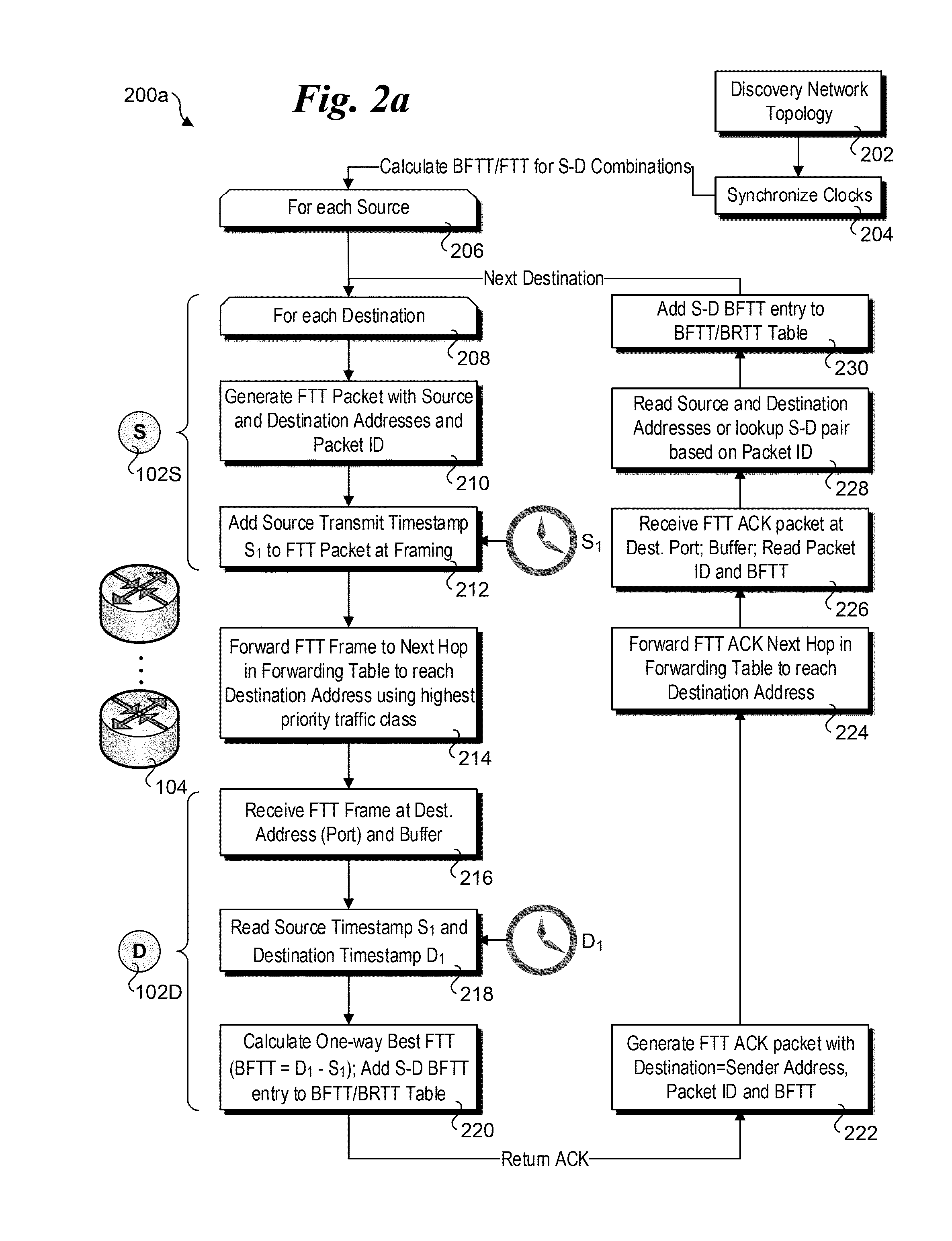
Methods, apparatus and software for implementing enhanced data center congestion management for non-TCP traffic. Non-congested transmit latencies are determined for transmission of packets or Ethernet frames along paths between source and destination end-end-nodes when congestion along the paths is not present or minimal. Transmit latencies are similarly measured along the same source-destination paths during ongoing operations during which traffic congestion may vary. Based on whether a difference between the transmit latency for a packet or frame and the non-congested transmit latency for the path exceeds a threshold, the path is marked as congested or not congested. A rate at which the non-TCP packets are transmitted along the path is then managed as function of a rate at which the path is marked as congested. In one implementation, non-TCP traffic is managed by mimicking a Data Center TCP technique, under which the congestion marking status of the path is substituted as an input to a DCTP algorithm in place of the normally-used ECN-Echo flag input. The congestion window output by the DCTCP algorithm is then used to manage the rate at which non-TCP packets to be forwarded via the path are transmitted from a source end-node.

Description

BACKGROUND INFORMATION[0001]In recent years, implementation of “cloud-based” services, high-performance computing (HPC) and other activities employing data centers and the like have seen widespread adoption. Under a typical data center installation, a large number of servers installed in server chassis and server racks are interconnected in communication using network links (e.g., Ethernet) and various switching mechanisms, such as switch blades / modules and “top-of-rack” (ToR) switches. In some installations, additional links, such as InfiniBand or Fibre Channel, may used for storage and other purposes.[0002]Performance of the network(s) within the data center can be impacted by congestion. During ongoing operations, applications running on compute nodes (typically hosted by physical servers and / or virtual machines, and also referred to as end-nodes, host nodes, or end hosts) send traffic to other applications using a “push” model under which a source node or host pushes traffic tow...

Claims


Application Information

Patent Timeline
IPC IPC(8): H04L12/801H04L12/26H04L12/807H04L12/911H04L47/27
CPCH04L47/18H04L47/822H04L47/27H04L43/0864H04L43/0894H04L12/4633H04L43/0858H04L43/16
Inventor NAOURI, YGDALSHARP, ROBERT O.KEELS, KENNETH G.MULTANEN, ERIC W.
Owner INTEL CORP
Learn More